
Sintering flue gas circulation method and device

A technology of sintering flue gas and circulation device, applied in lighting and heating equipment, waste heat treatment, furnaces, etc., can solve problems such as failure and negative impact on sintering production

Pending Publication Date: 2019-04-23
ZENITH STEEL GROUP CORP
View PDF7 Cites 1 Cited by
  • Summary
  • Abstract
  • Description
  • Claims
  • Application Information

AI Technical Summary

Problems solved by technology

However, due to the temperature or oxygen content of the circulating exhaust gas after the flue gas is circulated, it has a negative impact on the sintering production, resulting in some cases of flue gas circulation in factories and mines being unsuccessful.

Method used


Image

  • Sintering flue gas circulation method and device
  • Sintering flue gas circulation method and device

Examples


Embodiment 1

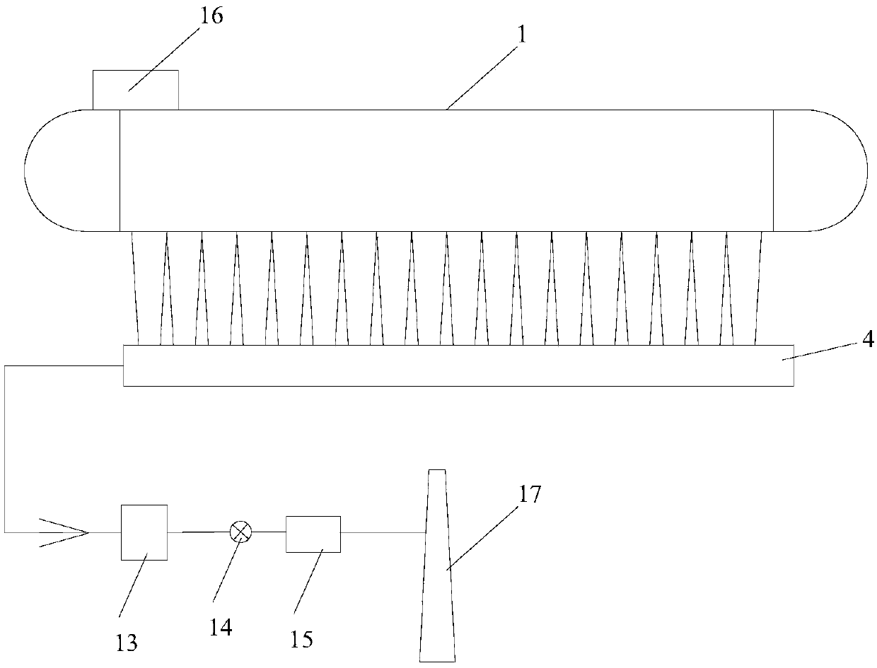
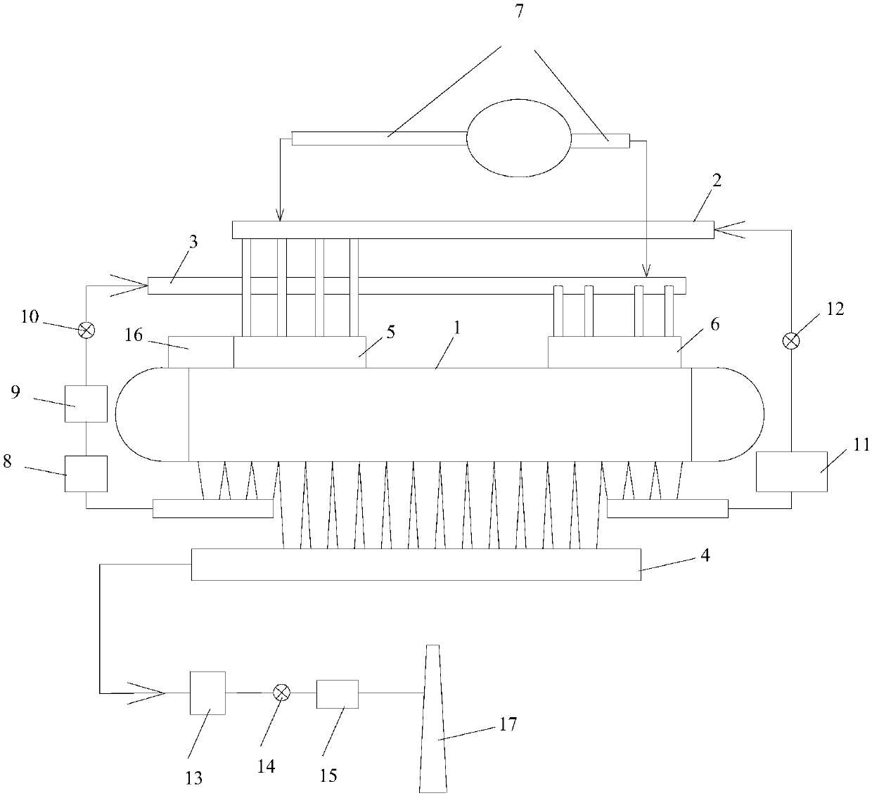
[0016] see figure 2 ( figure 1 with figure 2 The arrows in the figure represent the flow direction of oxygen or sintering flue gas), a sintering flue gas circulation device, including a sintering machine 1, a first circulating flue 2, a second circulating flue 3 and a main flue 4. The air inlet and outlet of the first circulating flue 2 are respectively connected to the air outlet of the wind box at the head of the sintering machine and the circulating flue gas hood 5 at the tail of the sintering machine, and the air inlet and outlet of the second circulating flue 3 They are respectively connected to the air outlet of the bellows at the tail of the sintering machine and the circulating flue gas hood 6 at the head of the sintering machine, and the air outlet end of the first circulating flue 2 and the air outlet end of the second circulating flue 3 are respectively connected to the oxygen pipe 7 , the air inlet of the main flue 4 is connected with the air outlet of the air ...

Embodiment 2

[0020] See figure 2 , this embodiment is basically the same as the sintering flue gas circulation device in Embodiment 1, the only difference is that: the wind box at the head of the sintering machine occupies 15% of the total length of sintering, and the wind box at the tail of the sintering machine occupies 15% of the total length of sintering. The sintering flue gas circulation method based on the sintering flue gas circulation device of this embodiment is as follows: the waste gas at the head of the sintering machine, which accounts for 15% of the sintering length, circulates to the tail of the sintering machine after dust removal and dehumidification; the oxygen content of the waste gas is 13 %, mixed with 10.8% of the exhaust gas with a concentration of 95% oxygen, and adjusted the oxygen content of the exhaust gas to 21%. The exhaust gas at the tail of the sintering machine, which accounts for 15% of the sintering length, circulates to the head of the sintering machine...


PUM


Abstract

The invention provides a sintering flue gas circulation method and device. Waste gas which accounts for 10%-20% of the sintering length at the head part of a sintering machine is circulated to the tail part of the sintering machine for use, and the waste gas which accounts for 10%-20% of the sintering length at the tail part of the sintering machine is circulated to the head part of the sinteringmachine for use. The oxygen content of the Waste gas at the head part is low, the oxygen content of the head and the tail circulating region is increased to 20%-25% level by adopting an oxygen-enriched technology, and the sintering condition of the sintering and the quality of the sintered ore are ensured. The invention provides the sintering flue gas circulation method and device, so that the sintering energy conservation and emission reduction are realized; and meanwhile, the oxygen-enriched technology is adopted, so that the production quality of the sintered ore is not influenced.

Description

technical field [0001] The invention belongs to the field of sintering emission reduction, in particular to a sintering flue gas circulation method and device. Background technique [0002] The sintering process in the iron and steel industry emits a large amount of pollutants, and flue gas circulation is an important way to reduce the total amount of emissions. A variety of recycling processes have been proposed and applied at home and abroad, such as LEEP, Epsint, EOS, selective flue gas recycling technology and Baosteel flue gas recycling technology. Some domestic steel mills such as Ninggang, Shagang, Yonggang, and Qiangang have carried out industrial applications. However, due to the problem of the temperature or oxygen content of the circulating waste gas after the flue gas is circulated, it has a negative impact on the sintering production, resulting in some cases of flue gas circulation in factories and mines being unsuccessful. In China, sinter is the most importa...

Claims


Application Information

Patent Timeline
IPC IPC(8): F27D17/00
CPCF27D17/002F27D17/008
Inventor 裴元东张俊杰陈军召吴献阳殷国富张巧玉盛建华李国良周晓冬段列平夏强
Owner ZENITH STEEL GROUP CORP
Learn More