Leg rehabilitation instrument

A technology for legs and patients, applied in the field of leg rehabilitation instruments, can solve the problems of inability to achieve the effect of rehabilitation training for the affected limb, inability to recover and train the affected limb, and stretching of the muscles of a single leg, so as to prevent muscle atrophy or adhesion. , The structure is simple, and the effect of preventing the decrease of joint mobility

Inactive Publication Date: 2019-04-26
CHANGZHOU TCM HOSPITAL
View PDF0 Cites 4 Cited by
  • Summary
  • Abstract
  • Description
  • Claims
  • Application Information

AI Technical Summary

Problems solved by technology

[0009] 1. Rehabilitation training is mainly carried out for the affected limb in the fourth stage, and the rehabilitation and training of the affected limb cannot be carried out from the first stage;
[0010] 2. The function of rehabilitation training is single, it can only assist walking alone, or exercise leg muscle stretching alone; it cannot achieve the best effect of rehabilitation training for affected limbs

Method used


Image

  • Leg rehabilitation instrument
  • Leg rehabilitation instrument
  • Leg rehabilitation instrument

Examples


Embodiment 1

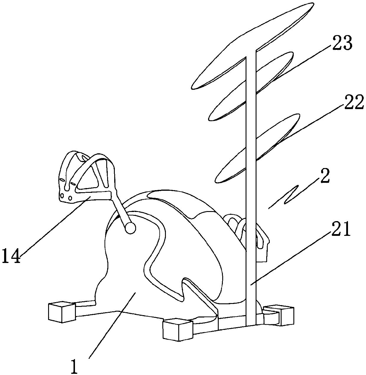
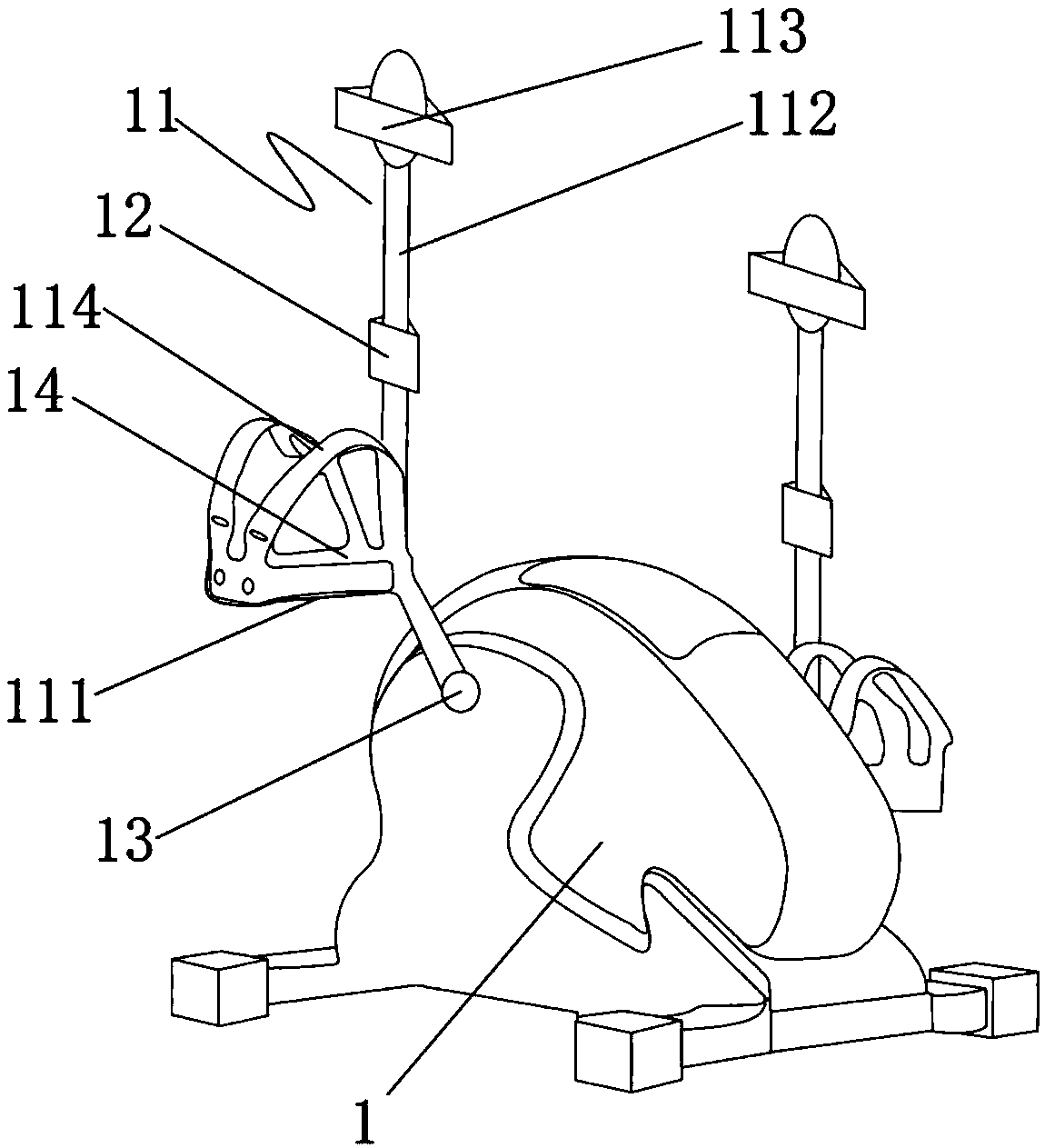
[0062] Such as figure 1 As shown, a leg rehabilitation instrument includes a body 1, a motor 6, a support frame 2, a power supply device 5 and a control device, the power supply device 5 provides power for the motor 6 and the control device, and the control device It is electrically connected with the motor 6, the motor 6 is arranged in the body 1, the support frame 2 is fixedly connected with the body 1, and is used to support and fix the upper body of the patient. The control device can be a PCB circuit board 4, on which a plurality of control circuits are arranged, which can control the operation of the motor 6, the operation of the resistance regulator 7, the operation of the activated electrode sheet 12 and so on. This kind of control circuit can adopt the PCB circuit board 4 control circuit on the market, which will not be repeated here.

[0063] The body 1 includes a pedal 14, a protective gear 11, an electrode sheet 12 and a resistance regulator 7. The pedal 14 is con...

Embodiment 2

[0075] The difference between this embodiment and embodiment 1 is:

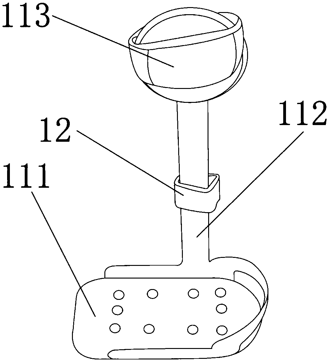
[0076] Such as Figure 4 As shown, the bottom bracket 111 and the support rod 112 are integrally formed, and the outside of the bottom bracket 111 and the support rod 112 is covered with a circle of L-shaped protective body 115, and the patient's feet are limited in the Inside the L-shaped protective body 115 .

[0077] By adopting the above-mentioned technical scheme, the entire lower limbs of the patient can be inserted into the covering space composed of the bottom bracket 111, the support rod 112 and the L-shaped protective body 115, so that the lower limbs can be more comprehensively limited and protected, and the whole lower limbs are more difficult Displacement, higher security.

Embodiment 3

[0079] The differences between this embodiment and embodiment 2 are:

[0080] The vertical rod 21 of support frame 2 is the support column air pressure lifting rod of pneumatic lifting self-locking telescopic height, and this support column air pressure lifting rod is vertically arranged, and is perpendicular to body 1 bottom plane.

[0081] By adopting the above-mentioned technical scheme, the vertical rod 21 is a support column pneumatic lifting rod with pneumatic lifting and self-locking telescopic height, and the patient can adjust the height of the vertical rod 21 according to his own height to ensure that the first ring 22 is adapted to the waist height of the patient. The second ring 23 is adapted to the shoulder height of the patient, thereby ensuring that the support frame 2 can better fix the patient's upper body.


PUM

PropertyMeasurementUnit
angleaaaaaaaaaa

Abstract

The invention discloses a leg rehabilitation instrument, which comprises a machine body, a motor, a support frame, a power supply device and a control device, wherein the machine body comprises a pedaling plate, a protection tool, an electrode plate and a resistance regulator; the pedaling plate is connected with the motor, and is driven by the motor to rotate; the resistance regulator is electrically connected with the control device and prevents the rotation of a motor fly wheel; the lower limb of a patient is limited and fixed by the protection tool; the electrode plate is fixed onto the inner side of the protection tool and is in contact with and connected with the lower limb of the patient; the support frame comprises a vertical rod, a first circular ring and a second circular; a plurality of first safety belts for fixing the waist of the patient are arranged on the first circular ring; a plurality of second safety belts for fixing the armpit and the shoulder of the patient are arranged on the second circular ring. The leg rehabilitation instrument has the advantages that the muscle equal length contraction training, passive training, active training and load bearing trainingcan be performed by the patients; various training measures are used for performing comprehensive rehabilitation on the sick limbs; the sick limbs are rehabilitated and trained from the first stage inthe whole process; the best sick limb rehabilitation effect can be reached.

Description

technical field [0001] The invention relates to the technical field of medical equipment, more specifically, it relates to a leg rehabilitation instrument. Background technique [0002] Clinically, most surgical patients stay in bed for a long time, or the disease treatment requires bed rest, which leads to inactivity or reduced range of activity of the leg muscles, resulting in decreased muscle tone, slowed venous return in the legs, and easy coagulation in the blood vessels to form thrombus. cause serious complications. [0003] Rehabilitation for a general leg fracture consists of four phases: [0004] The first stage, 1-2 weeks after the injury, during this period the injured limb is swollen, painful, the fracture end is unstable, and it is easy to redisplace; therefore, the main purpose of rehabilitation training in this period is to promote blood circulation of the affected limb to reduce swelling and stable fractures; [0005] The second stage is from 2 weeks after...

Claims


Application Information

Patent Timeline
Patent Type & Authority Applications(China)
IPC IPC(8): A61N1/36A61H1/02A63B22/08A63B23/04A63B21/22C09D183/04C09D175/04C09D7/61C09D7/63
CPCA61N1/36014A61H1/0214A61H1/0237A61N1/36003A63B21/00178A63B21/225A63B22/0605A63B23/04C08L2205/03C09D7/61C09D7/63C09D7/70C09D183/04C08L75/04C08L83/08C08K3/36C08K7/18C08K5/06C08K13/04
Inventor 吕志刚
Owner CHANGZHOU TCM HOSPITAL
Why Eureka
Try Eureka