
Multilevel pressurized gas stirring tank

A technology of pressurized gas and stirring tank, which is applied in the field of air stirring tank and multi-stage pressurized gas stirring tank, which can solve the problems of uneven stirring, stirring failure, and magnetic stirring strength is not as strong as mechanical stirring, so as to reduce mechanical stirring movement Components, cost-saving effect

Pending Publication Date: 2019-04-26
LIUPANSHUI NORMAL UNIV
View PDF0 Cites 0 Cited by
  • Summary
  • Abstract
  • Description
  • Claims
  • Application Information

AI Technical Summary

Problems solved by technology

Compared with the mechanical stirring method, the characteristic of magnetic stirring is that the stirring rotor is driven by magnetism, which is similar to mechanical stirring in essence, but the intensity of magnetic stirring is often not as strong as mechanical stirring, that is, there are certain limitations when dealing with large-volume containers. , because the stirring rotor of magnetic stirring is magnetic, so when dealing with minerals with a high iron content such as magnetism, a large number of magnetic minerals are wrapped on the stirring bar, which causes resistance to the operation of the rotor. Under the condition of weak magnetic driving force , not enough to drive a large number of mineral-coated rotors, which seriously causes problems such as uneven stirring and stirring failure, directly reducing the metal leaching efficiency

Method used


Image

  • Multilevel pressurized gas stirring tank
  • Multilevel pressurized gas stirring tank

Examples


Embodiment 1

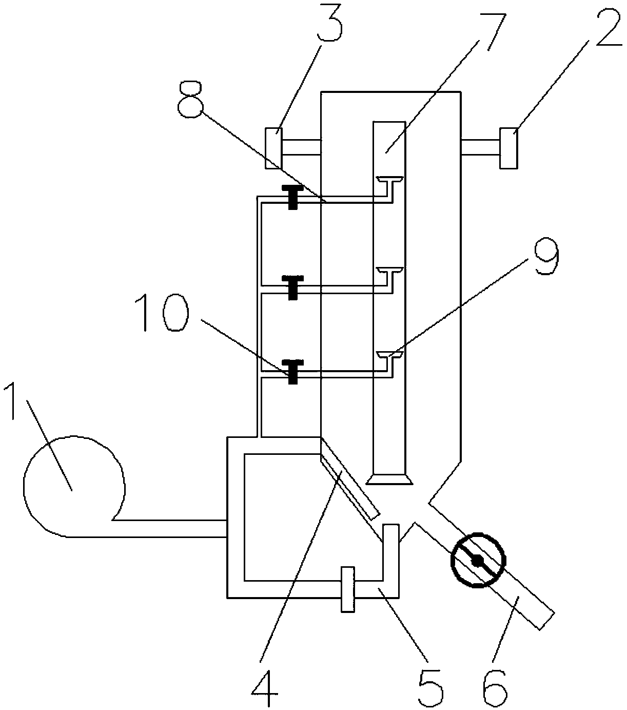
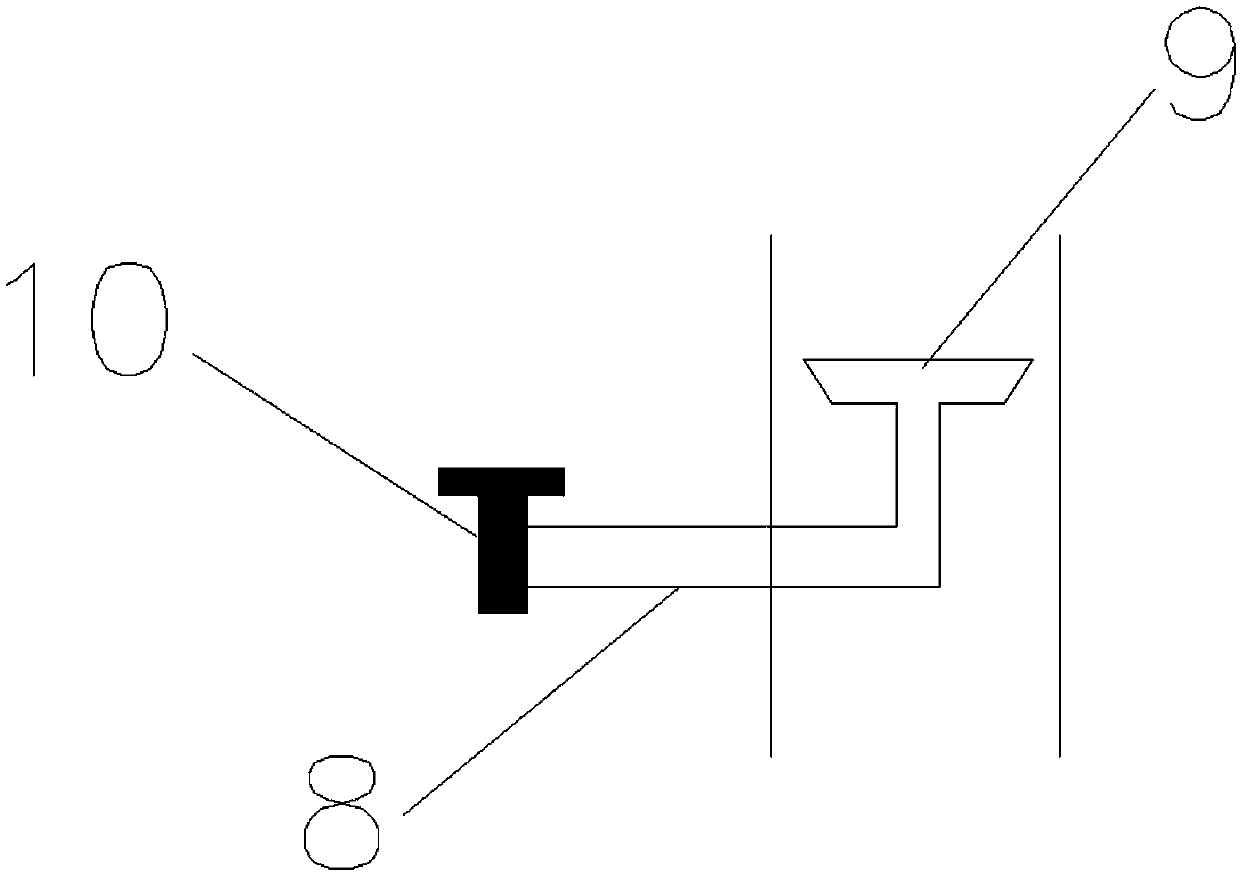
[0029] like figure 1 and 2 As shown, a kind of multi-stage pressurized gas mixing tank provided by the present embodiment includes: an air compressor 1, an upper ore pulp outlet 2, an ore pulp inlet 3, an air-assisted pipe 4 and an air explosion pipe respectively connected to the air compressor 1 5. It is characterized in that it also includes a central tube 7 arranged inside the gas stirring tank, and the pressure at the lower end of the central tube 7 is gradually increased by using multi-stage compressed air, and the ore slurry is gradually lifted to the upper part in the central tube 7 via the central tube 7 The outlet overflows, and then descends outside the central tube 7 to form a circular flow, and become a uniform slurry after several times of stirring.

[0030] In this embodiment, as figure 1 and figure 2 As shown, the stepwise increase of the pressure at the lower end of the central tube 7 by using multistage compressed air is realized by the following equipment...

Embodiment 2

[0033] In this embodiment, as figure 1 and figure 2As shown in the figure, similar to the first embodiment, the different technical solution is: enter the material to be stirred from the pulp inlet 3, and use the compressed air introduced from the bottom of the central pipe 7 by the air compressor 1 to drive the pulp in the central pipe 7 to rise to the central pipe. 7. The upper port overflows, and then descends outside the central pipe 7 to form a circulating flow. After many times of stirring, the slurry that is uniform or reaches the standard is transferred from the slurry outlet 2; the bottom of the stirring tank is conical and is provided with a sludge discharge pipe 6, Open the valve provided on the sludge discharge pipe 6 to remove the sludge accumulation at the bottom of the multi-stage pressurized gas stirring tank.

Embodiment 3

[0035] In this embodiment, as figure 1 and figure 2 As shown, similar to the first embodiment, the different technical solutions are: in this embodiment, as figure 1 and figure 2 As shown, the pressure regulating valve 10 adjusts the pressure at the end of the pressure pipe 8 at the position so that it becomes a certain constant pressure value.


PUM


Abstract

The invention discloses a multilevel pressurized gas stirring tank, and belongs to the technical field of metallurgical equipment. The multilevel pressurized gas stirring tank comprises an air compressor, an ore pulp outlet, an ore pulp inlet, an auxiliary gas pipe and an explosive gas pipe, the auxiliary gas pipe and the explosive gas pipe are respectively connected with the air compressor, the lower end of a center pipe arranged at the inner part of the pressurized gas stirring tank is connected with the auxiliary gas pipe, a plurality of pressure pipelines and air discs are connected in thecenter pipe, a plurality of pressure pipelines at the outer part of the center pipe are respectively connected with the air compressor through corresponding pressure regulation valves, the pressuresof the air discs connected with the plurality of pressure pipelines from top to bottom gradually increase, then an ore pulp gradually ascends in the center pipe, overflows through an upper opening ofthe center pipe, and then descends, and the ore pulp becomes even after being circularly stirred. The stirring equipment is high in degree of automation, simple in structure, strong in reliability andlow in fault rate, and is of great significance for intensifying leaching reaction kinetics and improving the application side of a leaching stirring device.

Description

technical field [0001] The invention relates to an air stirring tank, in particular to a multistage pressurized gas stirring tank, belonging to the technical field of metallurgical equipment. Background technique [0002] Leaching is a conventional technique in hydrometallurgy of valuable metals. Leaching is a multiphase reaction process of solid and liquid two phases, or even three phases of solid, liquid and gas. This process takes place on a solid surface and is affected by ion migration and diffusion. As far as the liquid and solid leaching process is concerned, the main steps are: (1) the inward diffusion of the leaching agent through the cracks of the ore particles; (2) the chemical reaction at the reaction point in the ore particles; (3) the outward diffusion of the dissolved substances into the solution. Obviously, in order to speed up the leaching process, stirring and leaching of finely ground materials has a great advantage, because the material is finely groun...

Claims


Application Information

Patent Timeline
Patent Type & Authority Applications(China)
IPC IPC(8): B01F5/10B01F13/02C22B3/02C22B3/04B01F33/40
CPCC22B3/02C22B3/04B01F25/51B01F33/40511Y02P10/20
Inventor 马爱元郑雪梅李松
Owner LIUPANSHUI NORMAL UNIV
Learn More