Novel full-automatic punching device with pipe visual inspection function

A technology of visual inspection and punching device, applied in the direction of feeding device, positioning device, storage device, etc., can solve the problems of surface grinding, low applicability, waste of labor and cost, etc., to avoid scratches and damage, The effect of providing processing efficiency and reducing maintenance costs

Pending Publication Date: 2019-04-26
广州英固特智能装备有限公司
View PDF0 Cites 6 Cited by
  • Summary
  • Abstract
  • Description
  • Claims
  • Application Information

AI Technical Summary

Problems solved by technology

[0002] Pipes are widely used in decoration, audio, luggage and various products. With the development of economy and society, each product has more and more requirements for pipe holes. Now the technology can no longer meet the needs of social development. need
In the existing pipe processing, when the pipe is automatically fed, the angle of placement will be deviated when it falls into the processing station, resulting in quality problems in subsequent pipe processing, wrong processing positions, and poor product quality, which is far from the quality requirements of the finished product. In the end, it can only be scrapped, and it will be a waste of manpower and cost to monitor whether there is any error in the placement angle position of the pipe after each feeding and correct it only by manpower.
Moreover, when the existing pipe is at the punching station, when the pipe pushing device pushes the pipe into the punching die, over-push and overpressure often occur, causing the surface of the pipe to be worn or damaged, affecting the processing quality of the product. The degree of automation is low, the structural design is unreasonable, the adjustment function and turning function of the pipe are not perfect, and the applicability is low
Complex structure, high failure rate, inconvenient maintenance, etc.

Method used


Image

  • Novel full-automatic punching device with pipe visual inspection function
  • Novel full-automatic punching device with pipe visual inspection function
  • Novel full-automatic punching device with pipe visual inspection function

Examples


Embodiment Construction

[0028] The technical solution of this patent will be further described in detail below in conjunction with specific embodiments.

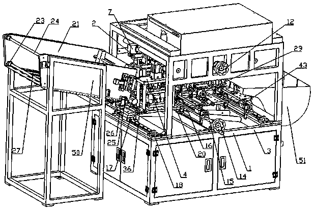
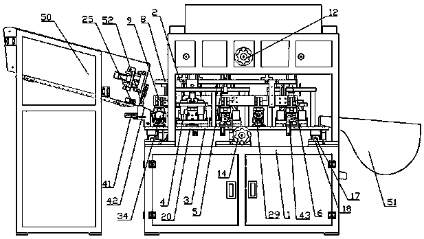
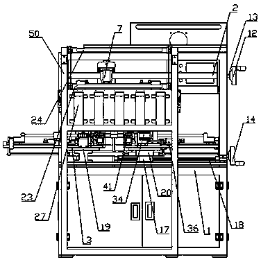
[0029] Such as Figure 1 to Figure 8 As shown, a new type of automatic punching device with pipe visual inspection, including a body 1, a feed funnel 50, an upper frame 2, a lower frame 3 and a discharge funnel 51; the feed funnel 50, the upper frame 2 , the lower frame 3 and the discharge funnel 51 are all arranged on the body 1; The end is connected with the feed station, the discharge station is provided with a discharge funnel 51, the upper frame 2 is located above the lower frame 3, and the upper frame 2 is provided with a transport assembly and a first adjustment assembly; the punching station is provided with There is a punching die, and the punching station includes a first punching station, a second punching station, a third punching station, the first punching station is provided with a first punching die 4, and the second punching stati...


PUM


Abstract

The invention discloses a novel full-automatic punching device with a pipe visual inspection function. The novel full-automatic punching device comprises a machine body, a feeding funnel, an upper rack, a lower rack and a discharging funnel. The feeding funnel, the upper rack, the lower rack and the discharging funnel are all arranged on the machine body. A feeding station, a punching station, a turnover station and a discharging station are arranged on the lower rack. Shaking plates, a pipe adjusting assembly and a jacking assembly are arranged on the feeding funnel, and the shaking plates are arranged at the bottom of the feeding funnel at intervals. A pipe visual inspection assembly is arranged at the feeding station. A punching mold further comprises a pipe pushing in-mold assembly, apipe waste clearing assembly and an oil supply lubricating device. The novel full-automatic punching device is suitable for carrying out punching on pipes of different types; automatic feeding and discharging are achieved; the machining efficiency is high; the problem of pipe collision is effectively solved; surface scratching and damage are avoided; the machining quality is high; demounting is convenient; problems happening to equipment in the production process can be found in time; maintenance is carried out rapidly; and the maintenance cost is reduced.

Description

technical field [0001] The invention relates to an automatic processing equipment, in particular to a novel full-automatic punching device with pipe visual detection. Background technique [0002] Pipes are widely used in decoration, audio, luggage and various products. With the development of economy and society, each product has more and more requirements for pipe holes. Now the technology can no longer meet the needs of social development. need. In the existing pipe processing, when the pipe is automatically fed, the angle of placement will be deviated when it falls into the processing station, resulting in quality problems in subsequent pipe processing, wrong processing positions, and poor product quality, which is far from the quality requirements of the finished product. In the end, it can only be scrapped, and it will be a waste of manpower and cost only to monitor whether there is an error in the placement angle position of the pipe after each feeding by manpower. ...

Claims


Application Information

Patent Timeline
Patent Type & Authority Applications(China)
IPC IPC(8): B21D28/28B21D28/34B21D43/04B21C51/00B21D43/10
CPCB21D28/28B21C51/00B21D28/34B21D43/04B21D43/105
Inventor 莫词英
Owner 广州英固特智能装备有限公司
Why Eureka
Try Eureka