
Circular hot cutter device adopting non-contact heating

A non-contact, hot knife technology, applied in metal processing and other directions, can solve the problems of inconvenient machining of the cutter shaft, troublesome installation, inability to realize the number and spacing of the cutters, etc. Simple installation and compact structure

Pending Publication Date: 2019-04-26
XI AN JIAOTONG UNIV
View PDF0 Cites 2 Cited by
  • Summary
  • Abstract
  • Description
  • Claims
  • Application Information

AI Technical Summary

Problems solved by technology

There are a small number of rotatable round hot cutting knives at home and abroad, all of which are heated by electric heating plate contact fixing method. When this round hot cutting knife rotates and cuts eagerly, the electric heating plate also rotates. Open a hole in the center of the cutter shaft and use a conductive ring to connect the connecting wire of the electric heating plate. Not only is the processing of the cutter shaft inconvenient, but also the installation is more troublesome. At the same time, due to the limitation of structure and material, it is impossible to achieve a large number of cutters and the spacing needs to be adjusted. requirements
In order to solve the above problems, the scientific and technological personnel of the scientific research unit continue to research and explore, and develop a new round hot cutter. Although some progress has been made in technology, there are still technical problems that have not been overcome in actual use.

Method used


Image

  • Circular hot cutter device adopting non-contact heating
  • Circular hot cutter device adopting non-contact heating
  • Circular hot cutter device adopting non-contact heating

Examples


Embodiment Construction

[0021] The present invention will be further explained below in conjunction with the accompanying drawings and specific embodiments. It should be understood that the following specific embodiments are only used to illustrate the present invention and are not intended to limit the scope of the present invention. It should be noted that the words "front", "rear", "left", "right", "upper" and "lower" used in the following description refer to the directions in the drawings, and the words "inner" and "outer ” refer to directions towards or away from the geometric center of a particular part, respectively.

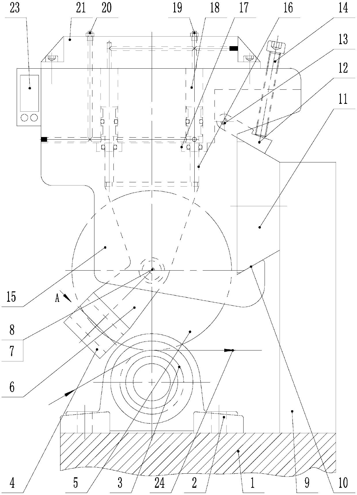
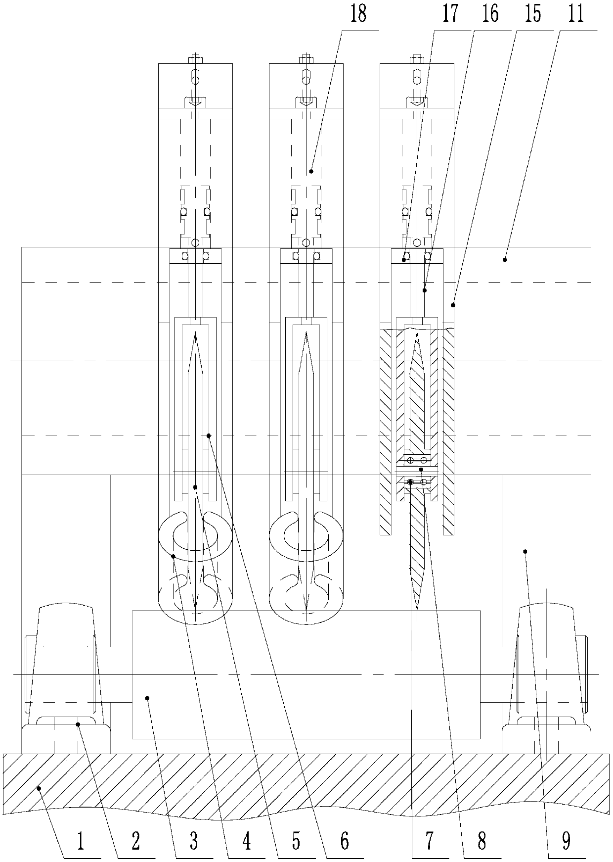
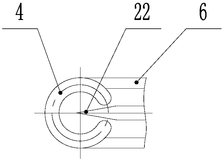
[0022] Such as Figure 1 to Figure 3 As shown, a non-contact heating circular hot knife device provided by the present invention includes a frame 1, a bearing with a seat 2, a bed knife shaft 3, an electromagnetic heating ring 4, a circular cutter 5, a support mounting seat 6, a bearing 7. Support shaft 8, guide rail bracket 9, dovetail groove 10, dovetail guide rail seat 11, ...


PUM


Abstract

The invention discloses a circular hot cutter device adopting non-contact heating. The circular hot cutter device adopting non-contact heating comprises a cylinder body, a rack, a bottom cutter shaftarranged above the rack in parallel, and a guide rail support vertically arranged on the rack, wherein the cylinder body is detachably connected with a sidewall above the guide rail support; and a plurality of cylinder barrels are arranged in the cylinder body in parallel, a piston rod is arranged in each cylinder barrel, a cylinder arranged in parallel is composed of a cylinder front gland and acylinder rear gland, an upper gas hole and a lower gas hole are further formed in the cylinder rear gland, and communicate with a gas inlet port and a gas outlet port of each cylinder separately, a bearing installation seat is fixedly installed at a stretching end of each piston rod, a circular cutter and an electromagnetic heating ring sleeving the cutter point of the circular cutter are movablyinstalled on each bearing installation seat, and an electromagnetic heating control box is further arranged on the cylinder body, and connected with each electromagnetic heating ring through an electric wire. The circular hot cutter device adopting non-contact heating realizes multi-cutter hot-pressing slitting machining with an adjustable temperature, an adjustable pressure and an adjustable breadth.

Description

technical field [0001] The invention relates to a cutting device, in particular to a non-contact heating circular thermal cutter device. Background technique [0002] In various industries such as clothing, shoemaking, leather, handbags, adhesive tape, papermaking, and automotive interiors, edge trimmers are often used to cut off edge materials or multi-knife slitters are used to batch wide bundles of various widths and specifications. Slitting job. According to the characteristics of material slitting and cutting, there are two ways of slitting: hot cutting and cold cutting. Hot cutting is the method of eliminating burrs by heating. At present, hot cutting is mainly based on fixed heating knives. The real hot cutting effect and high efficiency should be It is slitting with a circular knife that is automatically rotated by heating and pressing. There are a small number of rotatable round hot cutting knives at home and abroad, all of which are heated by electric heating pla...

Claims


Application Information

Patent Timeline
IPC IPC(8): B26F3/08B26D7/00
CPCB26D7/00B26F3/08
Inventor 王龙翔董寅雪翟大为
Owner XI AN JIAOTONG UNIV
Learn More