
Surface treater for electronic yarn drawing equipment

An electronic yarn and processor technology, applied in the field of electronic yarn drawing equipment, can solve problems such as unstable coating effect of sizing agent, failure to meet the production process, and influence on the oiling effect of tow, so as to improve the wind-shielding effect and reduce the distance , good coating effect

Active Publication Date: 2019-04-26
LINZHOU GUANGYUAN NEW MATERIAL TECH
View PDF6 Cites 0 Cited by
  • Summary
  • Abstract
  • Description
  • Claims
  • Application Information

AI Technical Summary

Problems solved by technology

[0002] After the sizing agent in the prior art enters the oiling box through the pipeline, the motor drives the roller to rotate, so that the sizing agent is evenly taken away by the rubber belt on the roller and evenly coated on the tow to achieve the oiling effect. The box cover is mainly used to block the spray water and prevent the powerful airflow around the bushing caused by the fast downward drive of the tow. When the tow passes through the rubber, the air flow at the rubber is too large, and the sizing cannot be better taken away by the rubber. Seriously Affect the oiling effect of the tow, so that the coating effect of the sizing agent is unstable and uneven, and in the process of use, the cover of the oiling box has a poor effect of blocking water spray and wind, which cannot meet the requirements of the production process

Method used

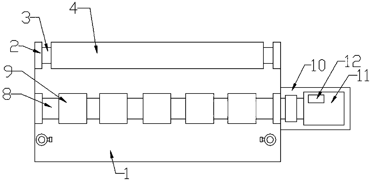

Image

  • Surface treater for electronic yarn drawing equipment
  • Surface treater for electronic yarn drawing equipment
  • Surface treater for electronic yarn drawing equipment

Examples


Embodiment 1

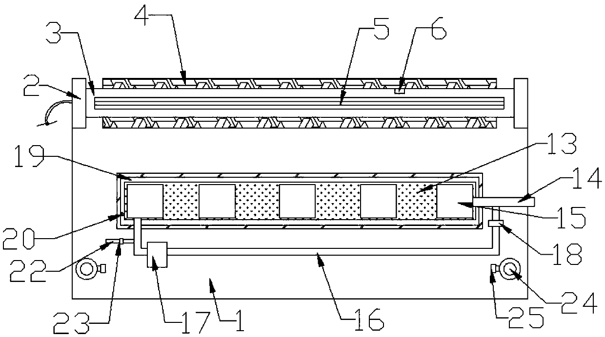
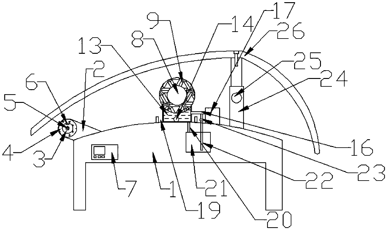
[0024] Such as Figure 1-3 As shown, a surface processor of an electronic yarn drawing equipment includes a workbench 1, a mounting seat 2, a rotating roller 8, a rubber sleeve 9, a servo motor 11, an oil box 13, and an arc-shaped oil cover 26. A receiving roller 3 is installed on the edge through the mounting seat 2. The receiving roller 3 is covered with a sponge-made suction jacket 4, and the receiving roller 3 is also installed with a low-temperature heating tube 5, and the middle of the workbench 1 is also installed The base 2 is equipped with a rotating roller 8, and a number of rubber sleeves 9 are sleeved on the rotating roller 8. One end of the rotating roller 8 is also connected to the output end of the servo motor 11 through a coupling, and the oil box 13 is installed on the rotating Below the roller 8, there are several oil ports 15 on the oil box 13, and the bottom end of each rubber sleeve 9 is close to an oil port 15, so that the rotating rubber sleeve 9 is impre...

Embodiment 2

[0029] Such as Figure 1-3 As shown, an oil inlet pipe 14 is connected below one end of the oil box 13, and the other end of the oil box 13 is connected to the oil inlet pipe 14 through an oil return pipe 16. An oil return pump 17 is installed on the oil return pipe 16. The oil tank 19 is divided into an oil tank 19, and the oil tank 19 is connected to an oil tank 21 through an oil accumulation pipe 20. The oil accumulation tank 21 is installed in the workbench 1, and the oil accumulation tank 21 is also connected to the oil return pipe 16 through a pipe 22.

[0030] The surplus wetting agent can enter the oil accumulation tank 21 through the oil tank 19, and be introduced into the oil inlet pipe 14 again through the oil return pump 17 and the oil return pipe 16, and return to the oil box 13 through the oil inlet pipe 14 for repeated use.

[0031] A first valve 18 is installed at the end of the oil return pipe 16 to control the on and off of the oil return pipe 16, and a second val...


PUM


Abstract

The invention discloses a surface treater for electronic yarn drawing equipment. The surface treater comprises a workbench, a mounting base, a rotating roller, rubber sleeves, a servo motor, an oil box and an arc oil cover, wherein a bearing roller is mounted at the edge of the workbench through the mounting base, the bearing roller is sleeved with a water absorption sleeve, the rotating roller isalso mounted at the middle part of the workbench through the mounting base, the rotating roller is sleeved with a plurality of rubber sleeves, the oil box is mounted below the rotating roller, a plurality of oil ports are arranged on the oil box, the bottom end of each rubber sleeve is tightly fitted with one oil port. According to the surface treater, the rubber sleeves dip-dye an impregnating compound through the oil ports, so that a yarn bundle can be evenly coated with the impregnating compound, the coating effect is good, and the coating is even; the bearing roller with the water absorption sleeve is arranged, so that the moisture in the yarn bundle is absorbed through the water absorption sleeve, then rubber of the rubber sleeves does not drip water; the distance between the arc oilcover and the workbench is reduced, so that the effects of keeping out a water spray and shielding wind of the arc oil cover are further improved.

Description

Technical field [0001] The invention relates to the technical field of electronic yarn drawing equipment, in particular to a surface processor of an electronic yarn drawing equipment. Background technique [0002] After the sizing agent in the prior art enters the oiling box through the pipe, the motor drives the roller to rotate, so that the sizing agent is evenly carried by the rubber belt on the roller and evenly coated on the tow to achieve the oiling effect. The box cover is mainly used to block the spray water and prevent the strong airflow around the leakage plate due to the rapid downward driving of the tow. When the tow passes through the rubber, the airflow at the rubber is too large, and the infiltration agent cannot be better taken away by the rubber. It affects the effect of tow oiling, so that the coating effect of the sizing agent is unstable and uneven, and in the process of use, the oiling box cover has a poor wind shielding effect and cannot meet the requirement...

Claims


Application Information

Patent Timeline
Patent Type & Authority Applications(China)
IPC IPC(8): C03C25/20
CPCC03C25/20
Inventor 李伟余启辉卢皓于万春
Owner LINZHOU GUANGYUAN NEW MATERIAL TECH
Learn More