
Vehicle five-phase permanent magnet fault-tolerant motor considering position sensor compensation

A permanent magnet fault-tolerant and sensor technology, which is applied to synchronous motors, magnetic circuits, and electric components with static armatures and rotating magnets. problems, to achieve the effect of improving the reverse salient rate, short winding ends, and reducing torque ripple

Inactive Publication Date: 2019-04-26
JIANGSU UNIV
View PDF2 Cites 6 Cited by
  • Summary
  • Abstract
  • Description
  • Claims
  • Application Information

AI Technical Summary

Problems solved by technology

[0004] In the prior art, the hybrid excitation fault-tolerant motor system based on position self-detection is proposed to greatly reduce the power density of the motor by setting multiple magnetic isolation layers along the direction of the q-axis magnetic circuit; For multi-phase motors, the number of pole pairs is relatively large, and the space for setting the magnetic isolation layer of the rotor is relatively small
In addition, the saturation phenomenon of the AC and direct axis armature reaction magnetic circuits of the five-phase permanent magnet fault-tolerant motor is serious, which brings greater challenges to the improvement of the saliency ratio of the motor

Method used


Image

  • Vehicle five-phase permanent magnet fault-tolerant motor considering position sensor compensation
  • Vehicle five-phase permanent magnet fault-tolerant motor considering position sensor compensation
  • Vehicle five-phase permanent magnet fault-tolerant motor considering position sensor compensation

Examples


Embodiment Construction

[0033] In order to make the object, technical solution and advantages of the present invention clearer, the present invention will be further described in detail below in conjunction with the accompanying drawings and embodiments. It should be understood that the specific embodiments described here are only used to explain the present invention, not to limit the present invention.

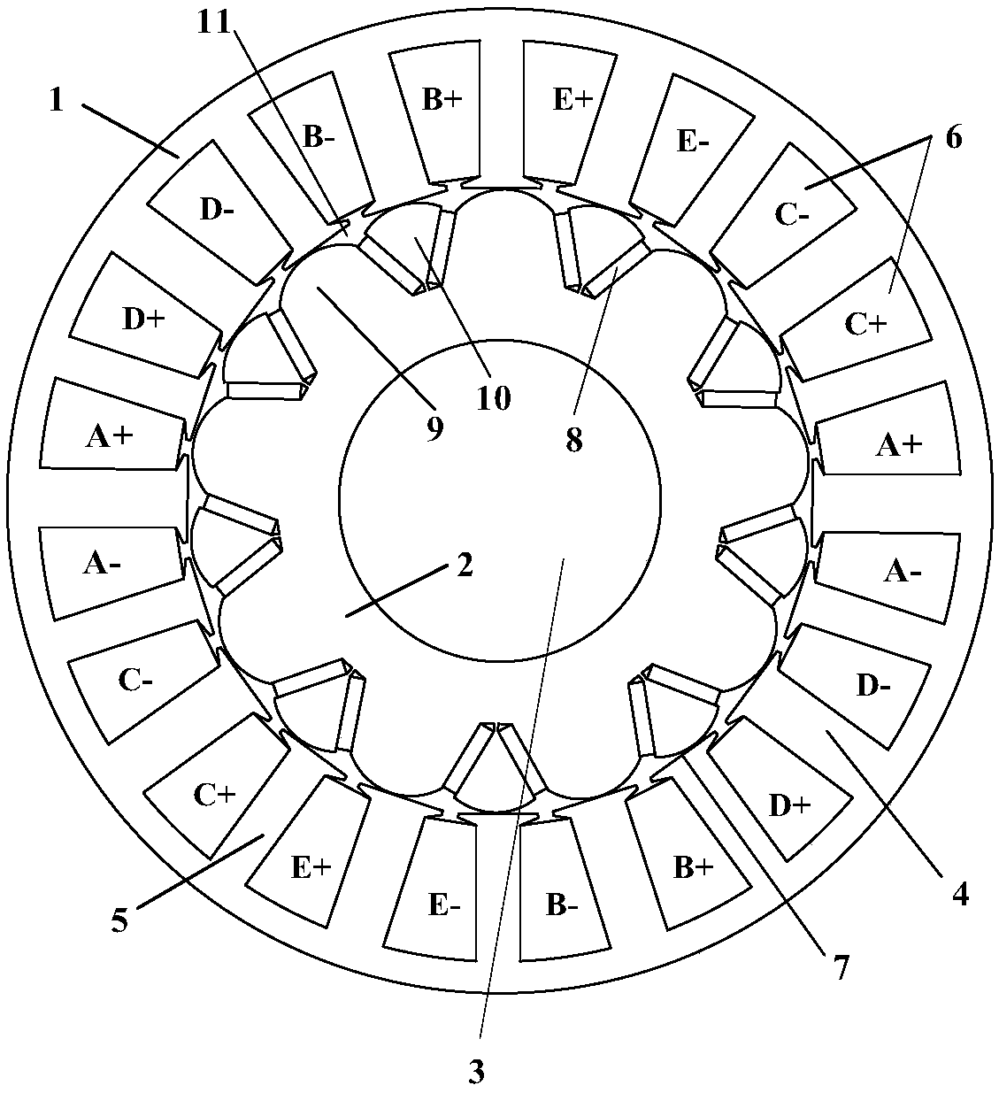
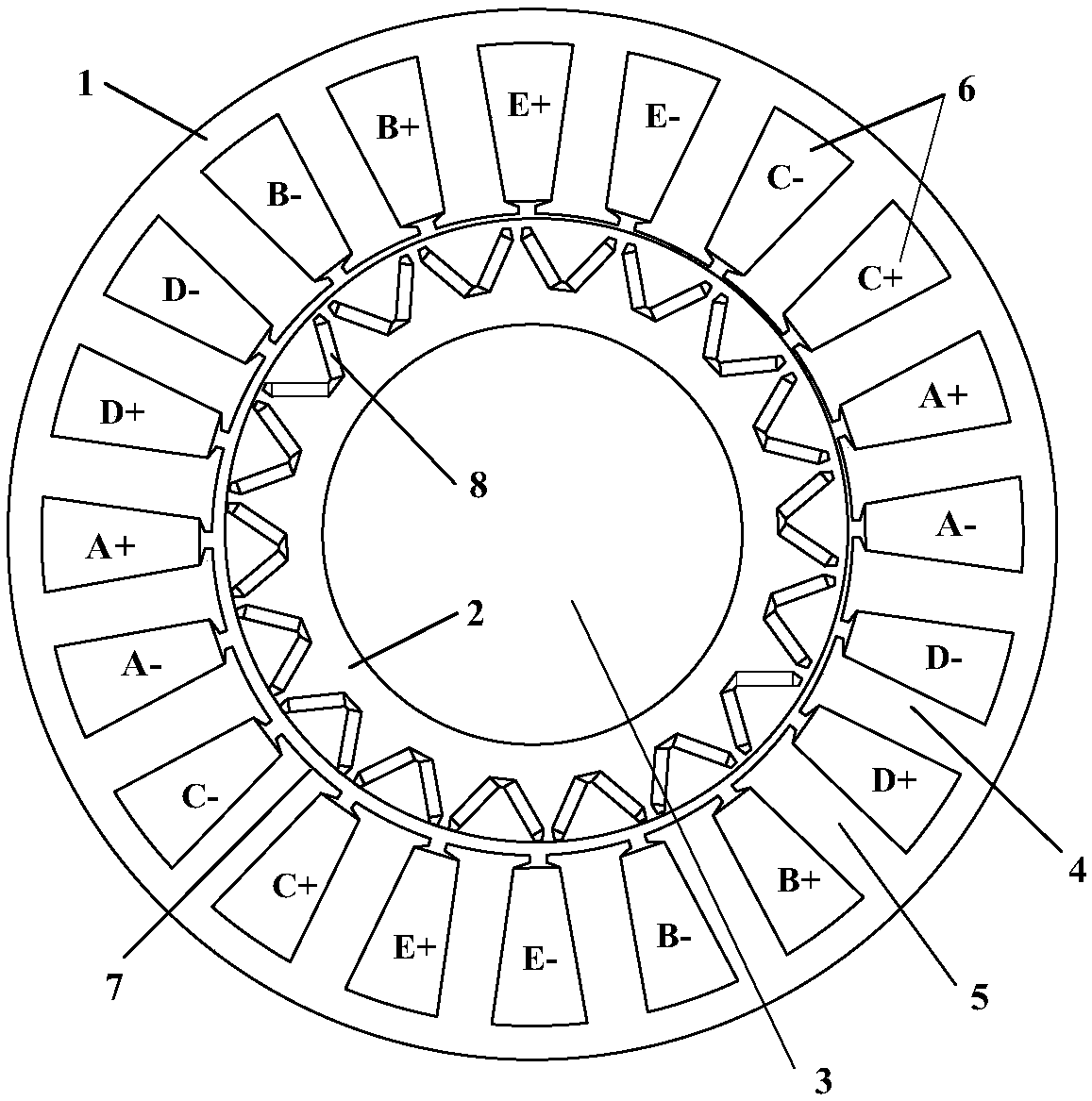
[0034] Such as figure 1 As shown, a vehicle-used five-phase permanent magnet fault-tolerant motor considering position sensor compensation proposed by the present invention includes a stator 1, a rotor 2 and a rotating shaft 3, the rotor 2 and the rotating shaft 3 are arranged coaxially, and the stator 1 is coaxially spaced. Set outside the rotor 2, the armature teeth 4 and fault-tolerant teeth 5 are evenly distributed along the inner circle of the stator 1, and the armature teeth 4 are wound with an armature winding 6, which is a single-layer concentrated winding, and two adjacent single-layer con...


PUM


Abstract

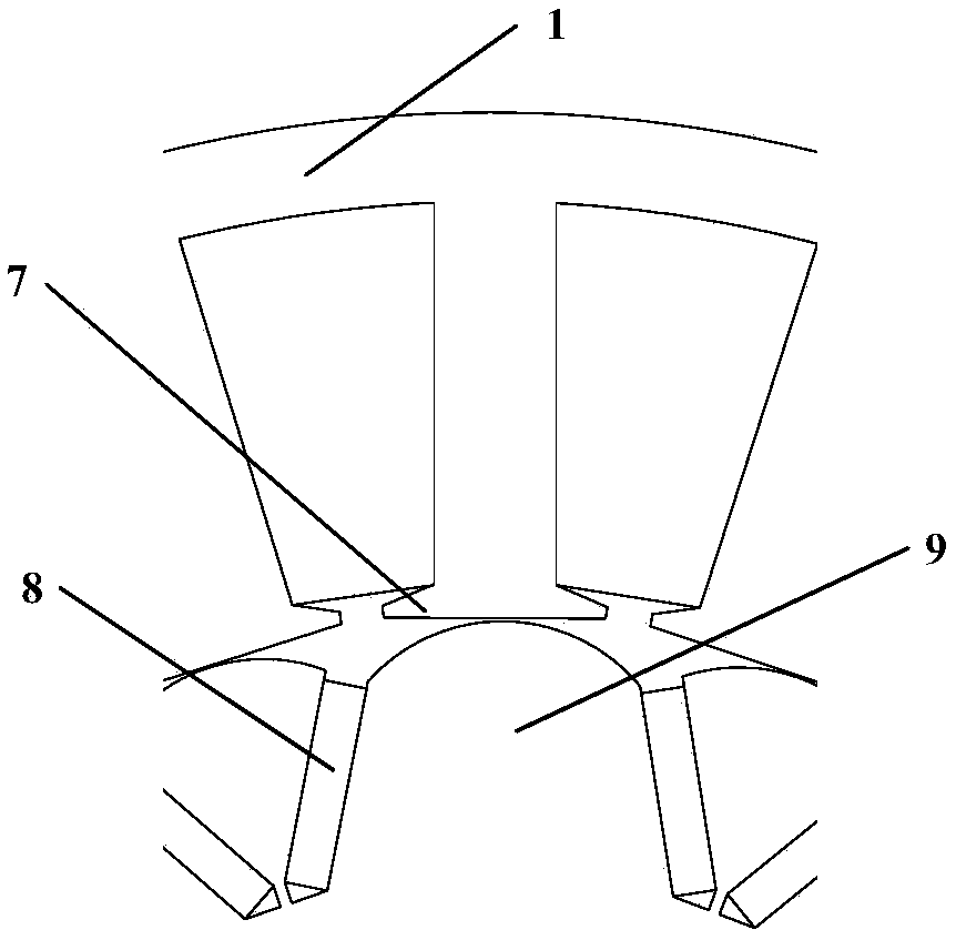
The invention discloses a vehicle five-phase permanent magnet fault-tolerant motor considering position sensor compensation. The vehicle five-phase permanent magnet fault-tolerant motor includes a stator, a rotor and a rotating shaft, armature teeth and fault-tolerant teeth are evenly distributed on an inner ring of the stator in the circumferential direction at intervals, armature windings are wound on the armature teeth, and every two adjacent armature windings are separated by the corresponding fault-tolerant teeth; the tooth width of the armature teeth are larger than that of the fault-tolerant teeth, and the tooth tops of the armature teeth and the fault-tolerant teeth are flattened; permanent magnets and iron core poles are arranged evenly in the circumferential direction of the rotor at intervals, the permanent magnets are placed in a V shape to form permanent magnet pairs, and V-shaped openings face air gaps; the iron core poles in the middles of the permanent magnet pairs aresecond iron core poles, the iron core poles between the adjacent permanent magnet pairs are first iron core poles, and the edges of the first iron core poles and the second iron core poles are all arcsurfaces; and air magnetic barriers are formed between the arc surfaces and stator teeth, zero low speed operation of five-phase permanent magnet fault-tolerant motor without position sensor controlcan be realized, and while improving basic performance of the motor, reliability and fault-tolerance performance of a motor driving system are further improved.

Description

technical field [0001] The invention belongs to the technical field of motors, and in particular relates to a five-phase permanent magnet fault-tolerant motor for vehicles considering compensation of position sensors. Background technique [0002] Five-phase permanent magnet fault-tolerant motors have the advantages of high efficiency, high power density, wide speed range, low torque ripple and strong fault tolerance, and have attracted extensive attention in the fields of electric vehicles and other fields. In addition to the motor itself, the motor drive system is also an important part of the controller and sensors. The failure of each part will affect the normal operation of the motor system, and even lead to the paralysis of the entire system and the occurrence of safety accidents. The position sensor in the motor drive system is also a component that is prone to failure, and the use of mechanical sensors reduces the reliability and robustness of the entire vehicle syst...

Claims


Application Information

Patent Timeline
IPC IPC(8): H02K21/14H02K1/27
CPCH02K1/2766H02K21/14
Inventor 张丽朱孝勇
Owner JIANGSU UNIV
Learn More