Electromagnetic valve structure for variable-lift air valve cam shaft

A technology for camshafts and solenoid valves, applied in valve devices, engine components, machines/engines, etc., can solve problems such as large coil turns of solenoids, solenoid valves that cannot meet actual needs, and complex structure of moving push rods. To achieve the effect of meeting control requirements, reducing cost and weight, and compact structure

Active Publication Date: 2019-04-30
JAPHL POWERTRAIN SYST
View PDF8 Cites 6 Cited by
  • Summary
  • Abstract
  • Description
  • Claims
  • Application Information

AI Technical Summary

Problems solved by technology

But present camshaft axially reciprocating solenoid valves have the following defects: 1. It is necessary to determine the action stroke position of the solenoid valve moving push rod under the action of the original sensor
2. At present, the solenoid valve with axial reciprocating motion of the camshaft does not make full use of the mechanical energy of the camshaft rotation to drive the pop-up action of the moving push rod. It needs to be driven by the magnetic force generated by the electromagnetic solenoid, which leads to the need for a larger winding for the solenoid. The number of turns of the wire needs to generate a large magnetic force to overcome the elastic force of the spring and drive the moving push rod at the same time
3. The structure of the moving push rod of the existing solenoid valve is complex and usually requires permanent magnets and laser welding processes
Therefore, the electromagnetic valve of engine camshaft in the prior art can't satisfy actual demand

Method used


Image

  • Electromagnetic valve structure for variable-lift air valve cam shaft
  • Electromagnetic valve structure for variable-lift air valve cam shaft
  • Electromagnetic valve structure for variable-lift air valve cam shaft

Examples


Embodiment Construction

[0022] Below with reference to the accompanying drawings, through the description of the embodiments, the specific embodiments of the present invention, such as the shape, structure, mutual position and connection relationship between the various parts, the role and working principle of the various parts, etc., will be further described. Detailed instructions:

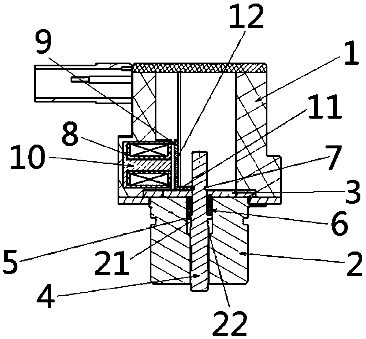
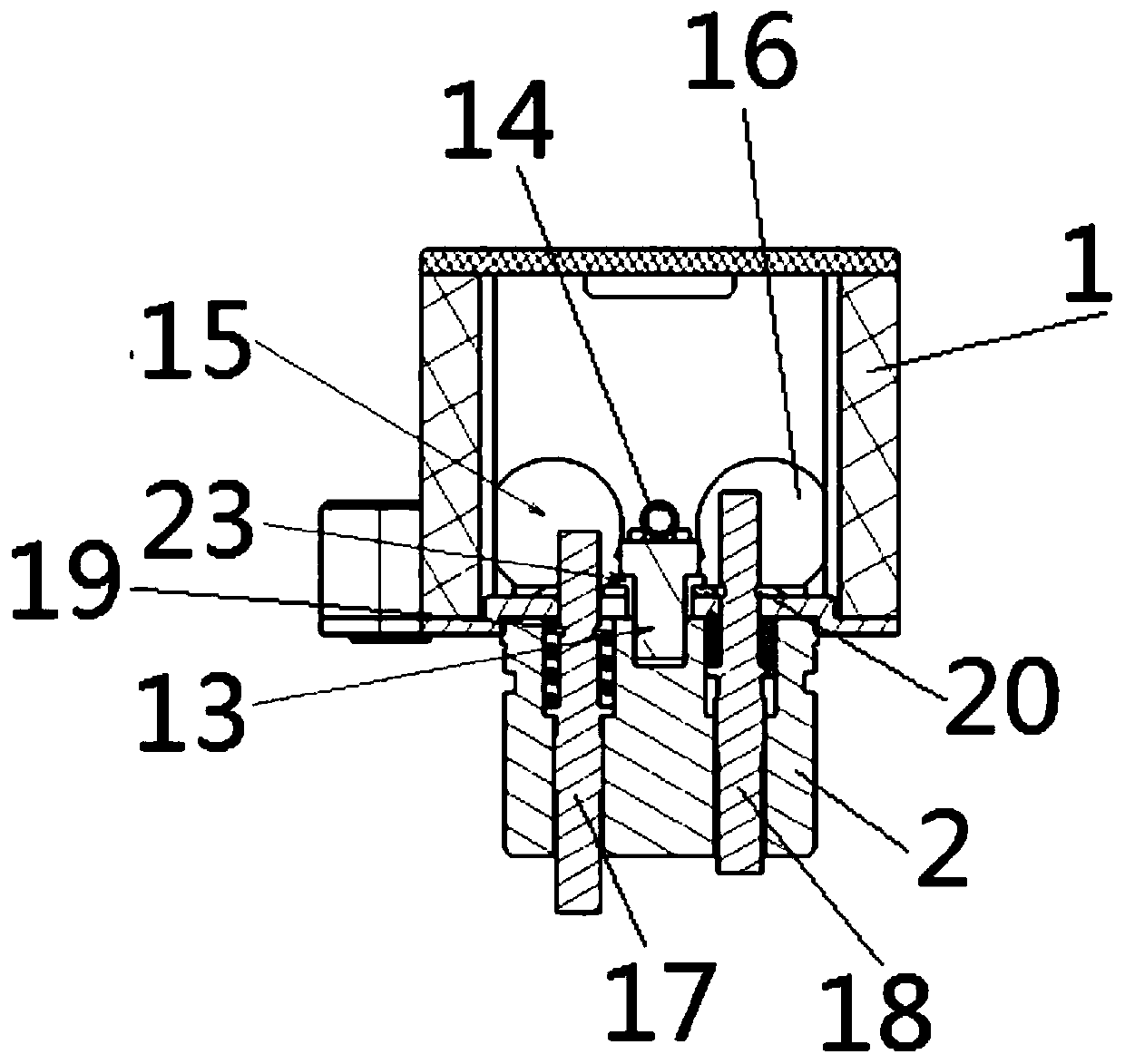
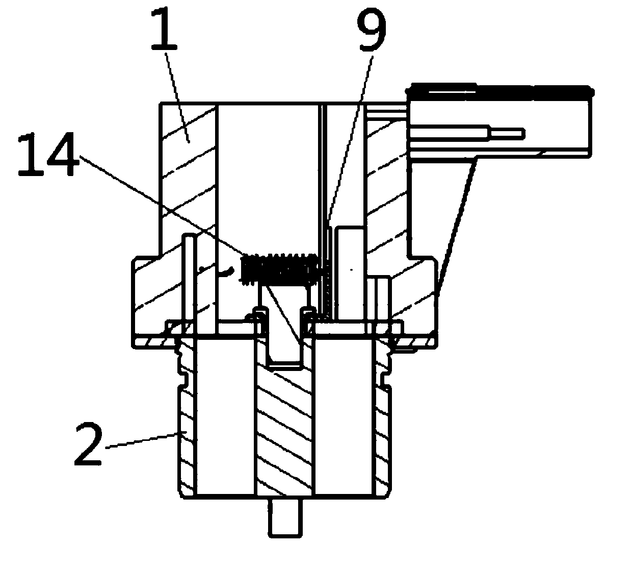
[0023] as attached figure 1 - attached image 3 As shown, the present invention is a solenoid valve structure for a variable lift valve camshaft, and the solenoid valve structure for a variable lift valve camshaft includes a valve body 1, a valve body 1 and a valve sleeve 2 Connection, a baffle 3 is set between the valve body 1 and the valve sleeve 2, one end of the moving push rod 4 moves through the valve sleeve 2 and the baffle 3 and extends into the valve body 1, and a protruding shoulder 5 is set on the moving push rod 4 One end of the compression spring 6 set on the moving push rod 4 is against the shaft should...


PUM


Abstract

The invention provides an electromagnetic valve structure for a variable-lift air valve cam shaft. The electromagnetic valve structure for the variable-lift air valve cam shaft is applied to the technical field of automobile engine parts, one end of a movable push rod (4) of the electromagnetic valve structure for the variable-lift air valve cam shaft movably penetrates through a valve sleeve (2)and a baffle (3) to extend into a valve body (1), one end of a compression spring (6) sleeving the movable push rod (4) abuts against a shaft shoulder (5), the other end of the compression spring (6)abuts against the baffle (3), a limiting clamp groove (7) is formed in one end of the movable push rod (4), the valve body (1) is internally provided with a solenoid (8) and a push rod buckle (9), anda magnetic core (10) is arranged in the solenoid (8). According to the electromagnetic valve structure for the variable-lift air valve cam shaft, extending and retracting control over the movable push rod of an electromagnetic valve can realized conveniently and reliably, limiting is effectively realized when the movable push rod retracts, response pop-up is realized quickly when the movable pushrod extends, and the demand for controlling an engine camshaft is met.

Description

technical field [0001] The invention belongs to the technical field of automobile engine components, and more specifically relates to a solenoid valve structure for a variable-lift valve camshaft. Background technique [0002] The solenoid valve of the camshaft is the actuator that drives the movement of the cam sleeve. It receives the signal from the automobile engine controller to control the moving push rod of the camshaft solenoid valve. In order to realize the axial movement of the sleeve, so as to achieve the purpose of adjusting the valve lift. But present camshaft axially reciprocating electromagnetic valve has the following defects: 1, need to determine the action travel position of electromagnetic valve moving push rod under the effect of sensor original. 2. At present, the solenoid valve with axial reciprocating motion of the camshaft does not make full use of the mechanical energy of the camshaft rotation to drive the pop-up action of the moving push rod. It nee...

Claims


Application Information

Patent Timeline
Patent Type & Authority Applications(China)
IPC IPC(8): F01L13/00
CPCF01L13/00F01L2013/0052F01L2013/101
Inventor 李振甄子源李后良丁万龙王友安方舫
Owner JAPHL POWERTRAIN SYST
Why Eureka
Try Eureka