
Brushless magnetic separation device and method

A technology of magnetic separation device and conversion device, which is applied in chemical instruments and methods, magnetic separation, solid separation, etc., can solve the problems of insignificant magnetic separation effect, influence of magnetic separation performance, and inability of magnetic material to be attracted by magnetic system brackets. Achieve good energy-saving effect and good demagnetization effect

Pending Publication Date: 2019-05-03
LIUPANSHUI NORMAL UNIV
View PDF8 Cites 1 Cited by
  • Summary
  • Abstract
  • Description
  • Claims
  • Application Information

AI Technical Summary

Problems solved by technology

However, the current utilization rate and resource utilization are less than 5%, and there is still a big gap between 75% and 90% of construction waste utilization in developed countries. If construction waste management is not strengthened, cities will be "sieged" or even "buried" by construction waste in the future. "
The application number is 201420800958.4, "a suspended magnetic separator": using a belt conveyor and a magnetic system support to achieve magnetic separation, this structure will cause the magnetic system support to be unable to pick up the magnetic material due to the material being transported on the belt conveyor is too thick, Magnetic performance will be affected by how much material is transported
"A flat-plate magnetic separator" with application number 201420341963.3: a leveling device is used to make the material more evenly distributed, so as to achieve better magnetic separation, but the leveling effect of the leveling device directly affects the magnetic separation effect. The material is too viscous, it is difficult to separate the magnetic material from other materials, so the magnetic selection effect is not obvious

Method used


Image

  • Brushless magnetic separation device and method
  • Brushless magnetic separation device and method
  • Brushless magnetic separation device and method

Examples


Embodiment Construction

[0019] The present invention will be further described below in conjunction with accompanying drawing.

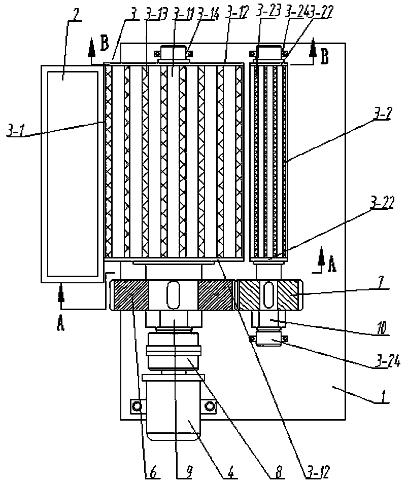
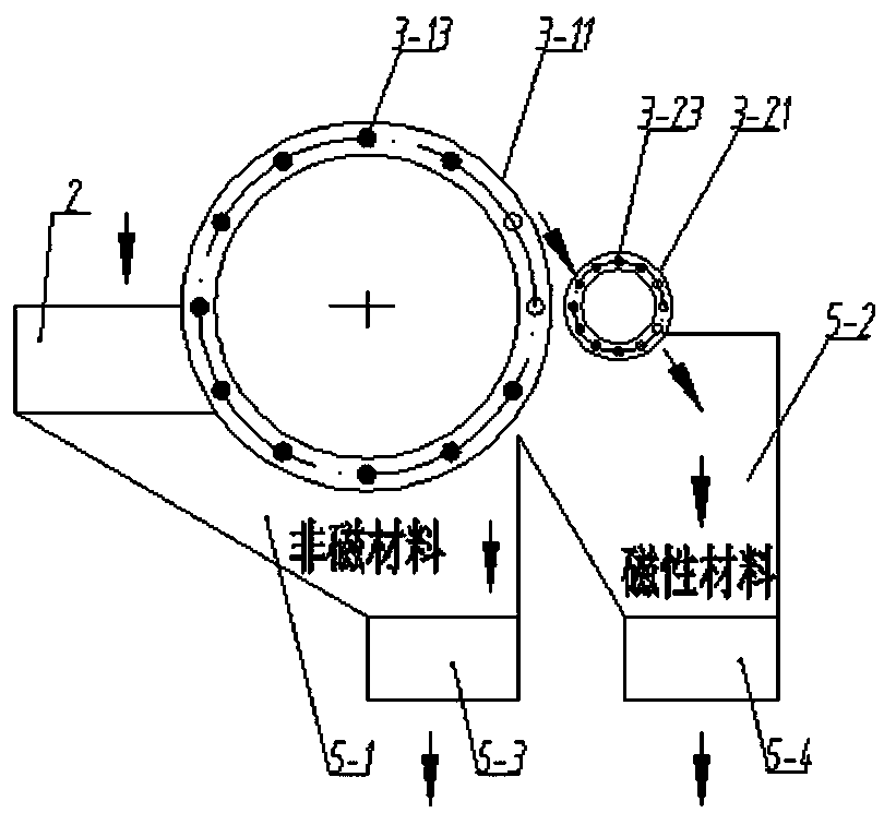
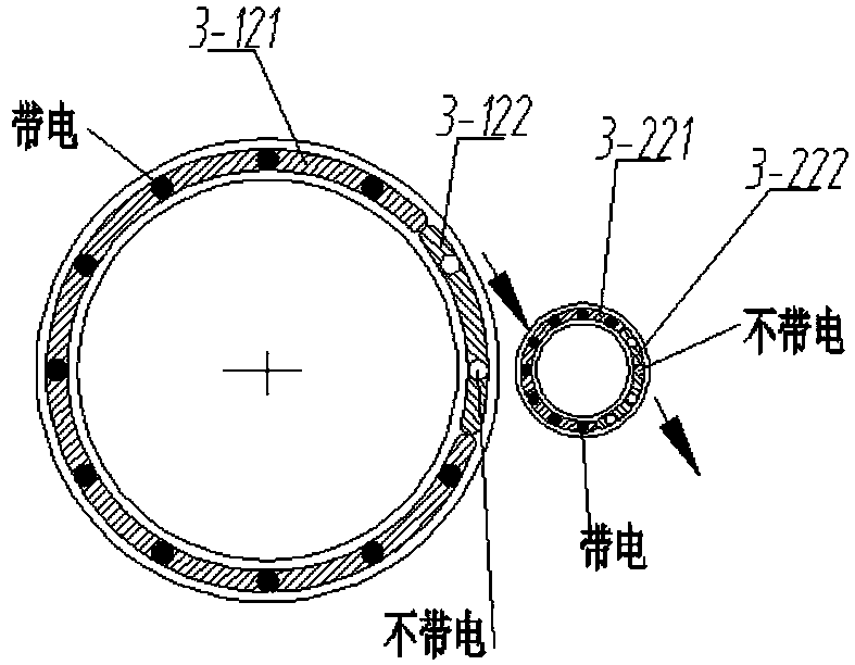
[0020] Such as Figure 1 to Figure 4 As shown, the brushless magnetic separation device includes a frame 1, a feed hopper 2, a magnetic separation device 3, a drive motor 4 and a distribution bin 5; the magnetic separation device 3 is located above the distribution bin 5, including a selection Iron device 3-1 and iron removal device 3-2, feed hopper 2 is positioned at the feeding side of iron selection device 3-1, and iron removal device 3-2 is positioned at the discharge side of iron selection device 3-1; The iron device 3-1 and the iron discharge device 3-2 are driven by the drive motor 4, and the iron selection device 3-1 and the iron discharge device 3-2 rotate in opposite directions; the material enters the distribution bin 5 from the feed hopper 2, and the non-ferrous The material is directly discharged from the outlet of the distribution bin 5, and the ferrous mater...


PUM


Abstract

The invention relates to a brushless magnetic separation device and method. The device comprises a rack, a feeding hopper, a magnetic separation device, a driving motor and a material separation bin.The magnetic separation device is arranged above the material separation bin and comprises an iron separation device and an iron discharging device, the feeding hopper is located at a feeding side ofthe iron separation device, and the iron discharging device is located at an discharging side of the iron separation device. The iron separation device and the iron discharging device are driven by adriving motor to operate and rotate oppositely. A material enters the material separation bin from the feeding hopper, wherein non-ferrous materials are directly discharged from a discharging openingof the material separation bin, and ferrous materials are adsorbed by the iron separation device, conveyed to the iron discharging device and conveyed to an iron discharging opening of the material separation bin through the iron discharging device for discharging. The magnetic discharge effect is good, and incomplete magnetic discharge caused by insufficient sweeping force is avoided. The magnetic separation part is of a double-roller structure, and has clear magnetic selection and magnetic discharge functions and materials are discharged from different channels. A single motor is used for driving in the magnetic separation process, and the energy-saving effect is good. A magnetic control device is adopted, and magnetic materials can be automatically sorted.

Description

technical field [0001] The invention relates to a magnetic separation device in the technical field of construction waste recycling engineering, in particular to a brushless magnetic separation device and a method. Background technique [0002] According to the "Regulations on the Management of Urban Construction Waste", construction waste refers to the construction units, construction units newly built, rebuilt, expanded and demolished various buildings, structures, pipe networks, etc. other waste. With the increase of my country's population and the rapid development of industrialization and urbanization, according to statistics, my country's annual production of construction waste is 3.5×10 9 t, and this data is still growing, and will reach 7.0×10 in the next few years 9 t. However, the current utilization rate and resource utilization are less than 5%, and there is still a big gap between 75% and 90% of construction waste utilization in developed countries. If cons...

Claims


Application Information

Patent Timeline
IPC IPC(8): B03C1/12
Inventor 包从望刘永志江伟朱广勇肖钦兰
Owner LIUPANSHUI NORMAL UNIV
Learn More