Automatic control method and device of magnetic separation column

A technology of automatic control device and magnetic separation column, which is applied in the direction of electrical program control, chemical instrument and method, sequence/logic controller program control, etc. Problems such as high cost, to achieve the effect of avoiding turning black or leaking ore, changing the size of the magnetic field, and protecting the balance of sorting

Active Publication Date: 2019-05-03
MASTEEL GRP MINING CO LTD
View PDF11 Cites 2 Cited by
  • Summary
  • Abstract
  • Description
  • Claims
  • Application Information

AI Technical Summary

Problems solved by technology

However, when it is applied to the sorting process of magnetic iron coarse concentrate, due to the influence of various process links such as grinding and grading, the amount of ore fed to it is unstable. Reasonable linkage adjustment of the valve and the bottom valve of the concentrate discharge pipe will cause the magnetic separation column to "fall", "turn over" or "run black", which will affect the technical indicators of iron selection
[0003] Although there are many devices or technologies for automatic control of magnetic separation columns in China, they basically use concentration sensors, current transmitters, electric actuators and other detection actuators. Due to their high cost, difficult maintenance and slow response , long-term operation accuracy decline and other problems, all failed to achieve long-term stable results in practice, and it is difficult to meet production requirements; and the application of PLC control, the use of appropriate bottom valve opening, and the rapid calculation of the appropriate bottom valve opening of the mine is the guarantee The key to stable operation of magnetic separation column and elutriation machine

Method used


Image

  • Automatic control method and device of magnetic separation column
  • Automatic control method and device of magnetic separation column
  • Automatic control method and device of magnetic separation column

Examples


Embodiment Construction

[0026] The following will clearly and completely describe the technical solutions in the embodiments of the present invention with reference to the accompanying drawings in the embodiments of the present invention. Obviously, the described embodiments are only some, not all, embodiments of the present invention. Based on the embodiments of the present invention, all other embodiments obtained by persons of ordinary skill in the art without making creative efforts belong to the protection scope of the present invention.

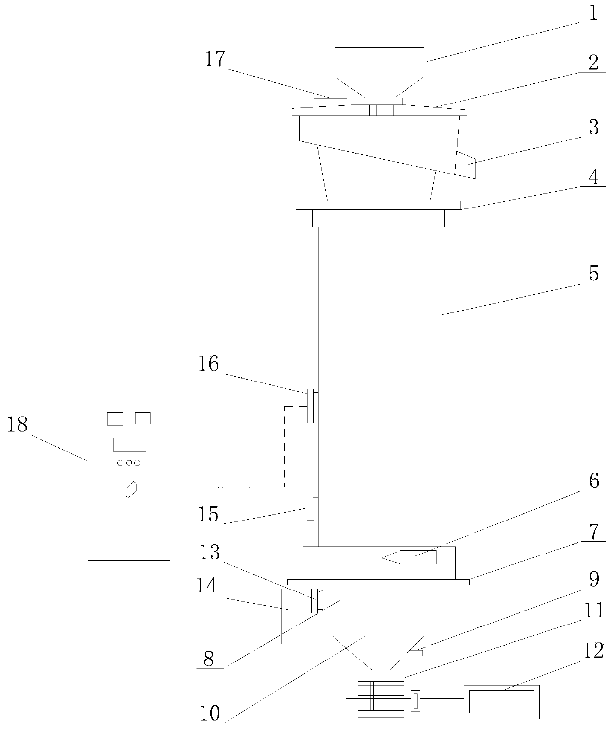
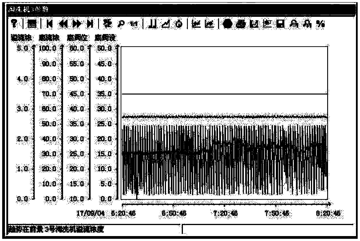
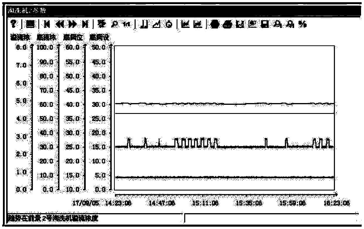
[0027] see Figure 2-5 , in the embodiment of the present invention: provide a kind of magnetic separation column automatic control method, comprise the following steps:

[0028] Step 1: Externally connect the electrical control cabinet 18 and the main junction box 16 on the magnetic separation column through the DP bus, and install the PLC system in the electrical control cabinet 18, and write the PLC control program;

[0029] Step 2: Determine the control r...


PUM


Abstract

The invention discloses a magnetic separation column automatic control method and a magnetic separation column automatic control device. According to the invention, an electric control cabinet is externally connected with a main junction box on a magnetic separation column through a DP bus. A PLC system is installed in the electric control cabinet. After that, the control range of a bottom valve on the magnetic separation column, input detection equipment, output equipment, control precision and response time are sequentially determined. According to the invention, the PLC system control is applied to an existing magnetic separation column structure. A proper opening degree of the bottom valve is adopted and the proper opening degree of the bottom valve in the ore is calculated rapidly. Therefore, the stable operation of the magnetic separation column or the elutriation machine is guaranteed. The problems that in traditional technical production, the magnetic separation column and theelutriation machine always change frequently, the algorithm response of an original plant to the bottom valve is slow and unstable, part of tailings can enter concentrate, and the grade of the iron concentrate is reduced are solved.

Description

technical field [0001] The invention relates to the technical field of iron concentrate beneficiation equipment control, in particular to an automatic control method and device for a magnetic separation column. Background technique [0002] Magnetic separation columns and elutriation machines are magnetic gravity separation equipment with electromagnetic low and weak pulsating magnetic fields, which have the advantages of strong separation ability for magnetite, small footprint, low power consumption, and reliable operation. It is used in various types of magnetite beneficiation plants; when it is used as the last process to obtain concentrate in the magnetite concentration section, since the associated process conditions of the magnetic separation column are basically stable, the improvement effect on the technical indicators of iron concentrate is obvious . However, when it is applied to the sorting process of magnetic iron coarse concentrate, due to the influence of vari...

Claims


Application Information

Patent Timeline
Patent Type & Authority Applications(China)
IPC IPC(8): B03C1/32G05B19/05
Inventor 许继斌
Owner MASTEEL GRP MINING CO LTD
Why Eureka
Try Eureka