
Simple abnormally-shaped test piece clamp and clamping method

A special-shaped and test piece technology, which is applied in the direction of manufacturing tools, grinding workpiece supports, grinding machine parts, etc. and other problems, to achieve the effect of small deformation of the device, small wear, and ensure the flatness

Inactive Publication Date: 2019-05-03
NORTHWESTERN POLYTECHNICAL UNIV
View PDF7 Cites 0 Cited by
  • Summary
  • Abstract
  • Description
  • Claims
  • Application Information

AI Technical Summary

Problems solved by technology

At present, the internationally recognized first choice to replace lead-tin solder is mainly concentrated on tin-silver-copper (Sn-Ag-Cu) alloy materials, which are prone to cause solder layer / metal-polymer quasi-brittle interlayer damage
At present, research on the interlayer failure of solder is also one of the hot spots in the field of packaging. At present, scholars at home and abroad mainly use lap joints when conducting interlayer damage tests on solder. The lap joint specimens are usually L-shaped for the convenience of clamping, and the welding surface It is difficult to grind. When using conventional fixtures, it is easy to cause a slope on the grinding surface when grinding the L-shaped test piece, and it cannot protect the non-grinding part of the L-shaped test piece during the grinding process. It is difficult to control the flatness of the grinding surface when grinding the welding surface

Method used


Image

  • Simple abnormally-shaped test piece clamp and clamping method
  • Simple abnormally-shaped test piece clamp and clamping method
  • Simple abnormally-shaped test piece clamp and clamping method

Examples


Embodiment Construction

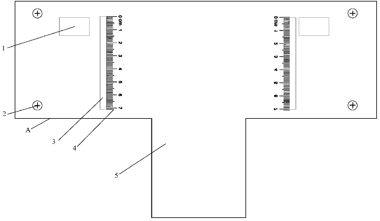
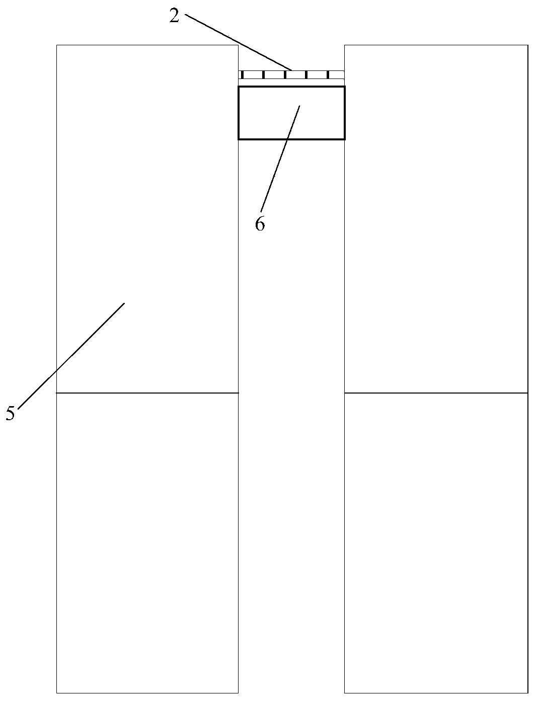
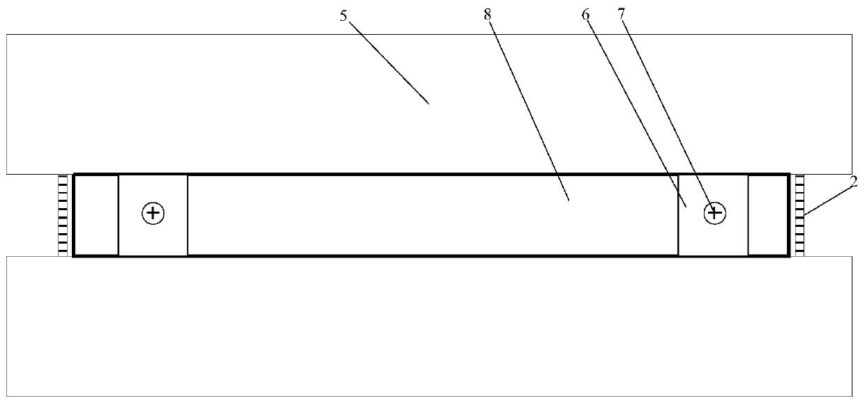
[0034] see figure 1 — Figure 12 , in order to recycle the lapped test piece, save the cost of the experiment, facilitate the grinding of the special-shaped test piece, ensure the smoothness of the polished surface of the test piece, ensure the accuracy of the test data, and provide an effective guarantee for the packaging test. The invention proposes a set of simple special-shaped test piece clamps for special-shaped overlapping test pieces, and the device can also be used for grinding conventional test pieces.

[0035] A set of simple clamping devices for special-shaped test pieces proposed by the present invention includes: two T-shaped clamps, four fixing bolts, two limiting bolts, two limiting plates, and a parallel plate. Among them, two observation holes are set on one of the T-shaped fixtures. The top of the observation hole is parallel to the bottom of the limit plate and the top of the parallel plate. The limit plate is inserted into the reserved limit plate hole of...


PUM


Abstract

The invention relates to a simple abnormally-shaped test piece clamp and a clamping method. The device is low in deformation, easy to process and form and high in strength and rigidity, the wear is little in the polishing process, and the test error can be reduced. The distance between two T-shaped clamps can be adjusted through bolts, the device can be used for polishing test pieces with different thicknesses, the thickness of each test piece which needs to be polished can be adjusted through limiting plates, the flatness of the polished face can be guaranteed, the frequency of the phenomenonthat due to the fact that the polished face is inclined, the test result is disturbed can be reduced, and therefore the accuracy of the test result is improved. According to the simple abnormally-shaped test piece clamp and the clamping method, polishing tools are in a T shape and are symmetrical, polishing can be conducted on the two sides, and the efficiency is improved.

Description

technical field [0001] The invention belongs to the field of electronic packaging, in particular to a simple special-shaped test piece fixture and a clamping method. Background technique [0002] The safety and reliability of electronic packaging technology has been paid more and more attention, and my country is also vigorously developing new sub-packaging technology, trying to gradually narrow the gap with the world's advanced level. Because the sintered nano-silver solder joint has good mechanical properties, weldability, electrical conductivity and thermal conductivity, it can meet the high-temperature and high-density packaging requirements of high-power semiconductor devices. And a lot of research and actual working conditions have shown that sintered nano-silver packaged devices can operate in environments such as high current density, extreme temperature and high-frequency vibration, and can better meet the requirements of microelectronic devices for aerospace vehicl...

Claims


Application Information

Patent Timeline
IPC IPC(8): B24B41/06B24B49/00
Inventor 姚尧宫贺王平
Owner NORTHWESTERN POLYTECHNICAL UNIV
Learn More