Automatic and rapid spiral location device for crankshaft, and use method thereof

A technology for positioning devices and crankshafts, applied to workpiece clamping devices, use feedback control, hand-held tools, etc., can solve the problems of high labor intensity and low work efficiency, achieve reduced labor intensity, good device versatility, and improved The effect of docking accuracy

Active Publication Date: 2019-05-03
GUANGXI YUCHAI MASCH CO LTD
View PDF5 Cites 1 Cited by
  • Summary
  • Abstract
  • Description
  • Claims
  • Application Information

AI Technical Summary

Problems solved by technology

[0003] The main purpose of the present invention is to propose an automatic and fast crankshaft circling positioning device with high degree of automation and high work efficiency, so as to solve the technical problems of low work efficiency and high labor intensity in the above-mentioned prior art

Method used


Image

  • Automatic and rapid spiral location device for crankshaft, and use method thereof
  • Automatic and rapid spiral location device for crankshaft, and use method thereof
  • Automatic and rapid spiral location device for crankshaft, and use method thereof

Examples


Embodiment 1

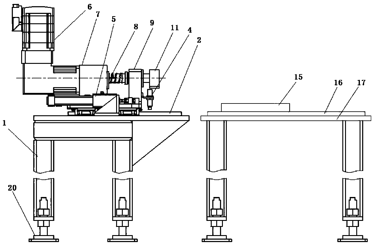
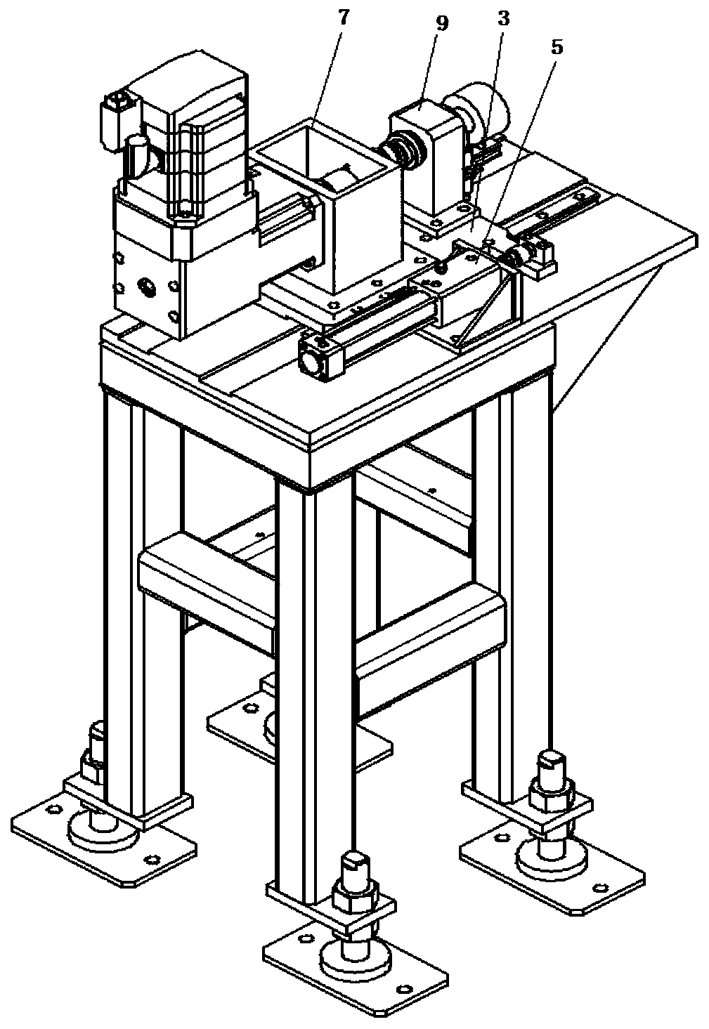
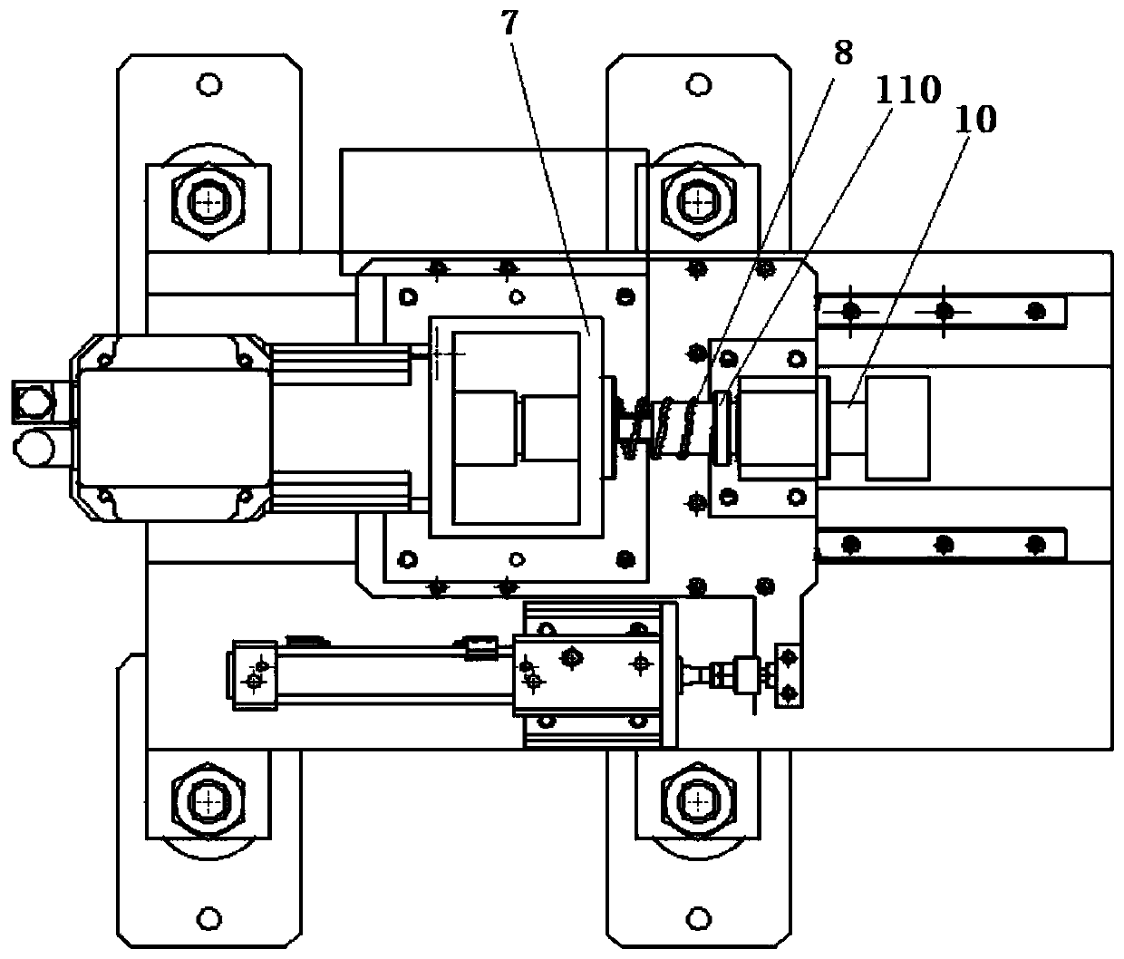
[0034] Such as Figure 1-6 The shown automatic and rapid crankshaft rotation positioning device includes a rotation mechanism and an assembly slide for fixing the engine arranged on the right side of the rotation mechanism. The hovering mechanism includes a support platform 1, a mounting plate 3, a cylinder 5, a support base 7, and a proximity switch 4. The mounting plate 3 is slidably connected with the upper surface of the support platform 1 through a sliding assembly, and is connected to the upper surface of the support platform 1 through the cylinder 5. The telescopic displacement drives the mounting plate 3 to reciprocate on the sliding device. The lower end of the supporting seat 7 is fixedly connected with the mounting plate 3 , and the upper end is provided with a servo motor 6 and a telescopic rotating shaft 10 connected with the servo motor shaft. The telescopic rotating shaft 10 is affected by the elastic member, so that it shrinks under the elastic force of the el...

Embodiment 2

[0047] The only difference between this embodiment and the first embodiment is that two square bosses 19 are arranged on the right end of the first connection base 11 , and the two square bosses 19 are one large and one small. Two bosses 19 of different sizes are provided to improve the linkage stability between the first connecting seat 11 and the second connecting seat, and at the same time, when the boss is aligned with the positioning square groove, it can be quickly inserted into the positioning square groove.


PUM


Abstract

The invention discloses an automatic and rapid spiral location device for a crankshaft, and a use method thereof. The automatic and rapid spiral location device for the crankshaft comprises a spiral mechanism and an assembly slide table, wherein the spiral mechanism comprises a support table, an installation plate, a cylinder, a bearing seat and a proximity switch, and the installation plate is slidably connected with the support table through a slide assembly, and driven to slide through the telescoping displacement of the cylinder; the lower end of the bearing seat is fixedly connected withthe installation plate, and a servo motor and a telescoping rotary shaft in shaft connection with the servo motor are further arranged at the upper end of the bearing seat; the telescoping rotary shaft is enabled to shrink and be stressed by the elasticity of an elastic element under the action of the elastic element; a first connection seat and a second connection seat are sequentially arranged at the tail end of the telescoping rotary shaft; and a signal device is fixed to the first connection seat, and the proximity switch is arranged below the signal device; and the proximity switch, the servo motor and the cylinder are in signal connection with a controller. The automatic and rapid spiral location device for the crankshaft has the advantages of being high in automation degree, high inworking efficiency, low in the labor intensity of installation for a piston connection rod, and the like.

Description

technical field [0001] The invention relates to the technical field of assembly of engine crankshaft accessories, in particular to an automatic and rapid crankshaft rotation positioning device and a method for using the same. Background technique [0002] The piston connecting rod group converts the reciprocating motion of the piston into the rotational motion of the crankshaft, and at the same time converts the force acting on the piston into the output torque of the crankshaft to drive the wheels of the car. Pistons and connecting rods are key components of an engine. When assembling the piston connecting rod, the crankshaft needs to be rotated at a certain angle every time the piston connecting rod is assembled, so that the connecting rod neck protrudes out of the cylinder bore so as to facilitate the assembly of the connecting rod and the connecting rod cover. At present, in production practice, the piston rod assembly is performed by manually rotating the crankshaft, w...

Claims


Application Information

Patent Timeline
Patent Type & Authority Applications(China)
IPC IPC(8): B25B27/00B25B11/00G05D3/12
CPCY02T10/40
Inventor 卢福才覃大仓李厚波戴剑伟龙福海陈太优
Owner GUANGXI YUCHAI MASCH CO LTD
Why Eureka
Try Eureka