
U-shaped device for steel frame processing

A steel skeleton, U-shaped technology, applied in the field of steel bar processing, can solve the problems of difficult construction quality, lazy reduction of process operation space, large labor input, etc., to facilitate the sampling inspection and acceptance of finished products, avoid cutting corners, and reduce work time.

Active Publication Date: 2020-09-25
GUANGDONG BOZHILIN ROBOT CO LTD
View PDF10 Cites 0 Cited by
  • Summary
  • Abstract
  • Description
  • Claims
  • Application Information

AI Technical Summary

Problems solved by technology

[0003] However, such a construction operation requires a large number of on-site human resources. Specifically, a large number of manual binding operations are carried out on the construction work surface such as the operation floor, which requires a large labor input and a long construction period. Large, usually due to stampede caused dislocation of steel bars, insufficient protective layer of steel bars, etc., resulting in serious engineering problems such as floor cracking, exposed steel bars, etc.
Moreover, the construction quality of traditional crafts depends on the work of the construction team, but the construction team is uneven, and there is a certain flow of personnel, so it is not easy to control the uniform construction quality
In addition, the traditional operation mode gives the construction team more room for cutting corners or being lazy to reduce the process.

Method used


Image

  • U-shaped device for steel frame processing
  • U-shaped device for steel frame processing
  • U-shaped device for steel frame processing

Examples


Embodiment Construction

[0029] In order to make the above-mentioned purpose, features and advantages of the present application more obvious and understandable, the specific implementation manners of the present application will be described in detail below in conjunction with the accompanying drawings. In the following description, numerous specific details are set forth in order to provide a thorough understanding of the application. However, the present application can be implemented in many other ways different from those described here, and those skilled in the art can make similar improvements without departing from the connotation of the present application, so the present application is not limited by the specific embodiments disclosed below.

[0030] It should be noted that when an element is referred to as being “fixed on” or “disposed on” another element, it may be directly on the other element or there may be an intervening element. When an element is referred to as being "connected to" a...


PUM


Abstract

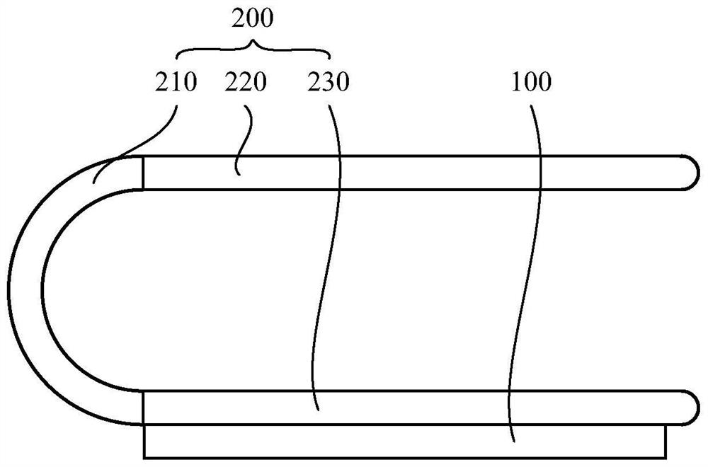
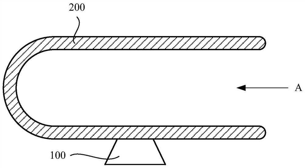
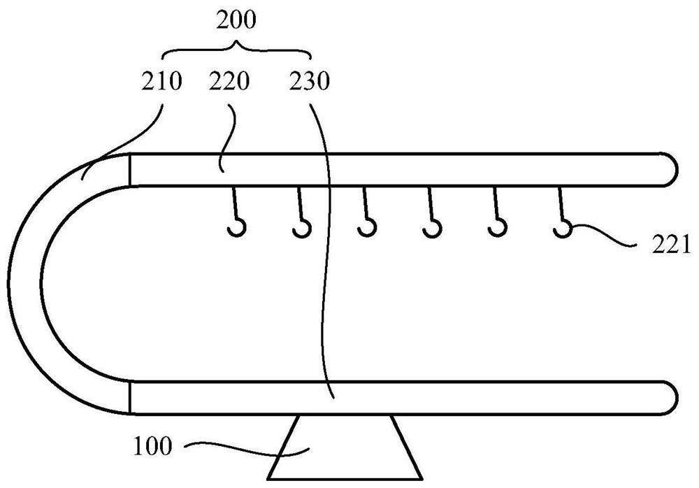
The invention relates to a U-shaped device for steel reinforcement framework processing. The U-shaped device comprises a base and a U-shaped table board. The U-shaped device has the advantages of being simple in structure and convenient to use. When the U-shaped device is in use, a steel reinforcement to be processed is placed on a bearing plate so that the steel reinforcement to be processed canbe fixed well through cooperation of a matching plate to facilitate placing and position of the steel reinforcement to be processed while the bearing plate well bears the steel reinforcement to be processed, operation of construction personnel can be simplified, operation workloads of the construction personnel can be relieved, and then the construction personnel can assemble steel reinforcementsand semi-finished steel reinforcement products or semi-finished reinforcement framework products into reinforcement frameworks which can be taken and used instantaneously. The production quality of unified reinforcement frameworks can be controlled easily. Moreover, the U-shaped device can also output the reinforcement frameworks at the construction location for direct use. Accordingly, the requirements for the construction personnel are reduced, the construction quality of the reinforcement frameworks is effectively improved, the operation time of a construction working face of reinforced barengineering is shortened, and the construction speed is increased. Moreover, finished products can be subjected to casual inspection and acceptance inspection conveniently, the phenomenon of cheatingon workmanship and materials during reinforced bar engineering is avoided, and the construction quality is ensured.

Description

technical field [0001] The application relates to steel bar processing, in particular to a U-shaped device for steel bar skeleton processing. Background technique [0002] At present, for the construction of steel bars in domestic engineering projects, steel bar processing workshops are usually set up on the project site to process the steel bars, and then transported to the construction work surface for steel bar binding and welding; among them, the steel bar raw materials mainly include straight strips and coils of various specifications. Strip raw materials, etc.; the processing includes cutting and forming, etc., and forming includes bending, cutting, forming of main bars and stirrups, etc. Most of the steel bar binding and welding work in the traditional process is completed on the construction surface. The specific technological process is as follows: 1) Manual lofting of steel bars; 2) Cutting and forming of steel bars based on manual operations; 3) Transportation of...

Claims


Application Information

Patent Timeline
Patent Type & Authority Patents(China)
IPC IPC(8): B25H1/00B25H1/08
Inventor 孙军杨泓斌黄万禧刘博蔡晓涛
Owner GUANGDONG BOZHILIN ROBOT CO LTD
Learn More