Sucking disk clamping device and method for pushing tanks

A clamping device and suction cup technology, applied in packaging, packaging bottles, transportation and packaging, etc., can solve the problems of high cost, low cost performance, high price, etc., and achieve the effect of avoiding frequent positive and negative rotation and simple structure

Inactive Publication Date: 2019-05-03
CHANGAN UNIV
View PDF7 Cites 0 Cited by
  • Summary
  • Abstract
  • Description
  • Claims
  • Application Information

AI Technical Summary

Problems solved by technology

[0002] Packaging machinery is mainly used in the field of food machinery such as liquor, beer, vinegar, soy sauce, etc. In bottle or can packing machinery, the traditional movement of bottles and cans is realized by belt transmission or chain transmission, and stepper motors or servo motors are required Repeated forward and reverse, large loss, high cost, complex technology
The grasping and loosening of bottles and cans is accomplished by mechanical claws, which require a large number of motors, difficult control, high price, and low cost performance

Method used


Image

  • Sucking disk clamping device and method for pushing tanks
  • Sucking disk clamping device and method for pushing tanks
  • Sucking disk clamping device and method for pushing tanks

Examples


Embodiment Construction

[0029] The technical solution of the present invention will be further described below in conjunction with the accompanying drawings and specific embodiments.

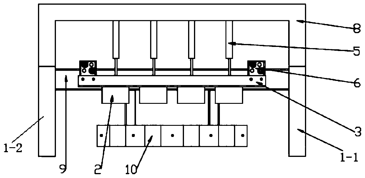
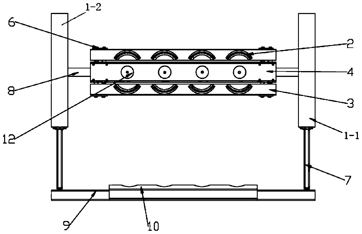
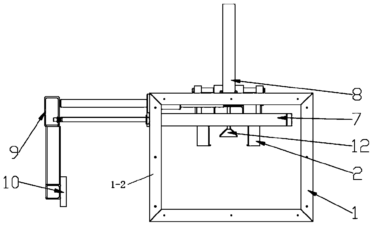
[0030] The invention provides a tank container push tank suction cup clamping device, such as Figure 1-Figure 4 As shown, it includes two symmetrically arranged racks, which are respectively the first rack 1-1 and the second rack 1-2, the first rack 1-1 and the second rack 1-2 are rectangular frames, A second telescopic cylinder 7 is respectively arranged on the inside of the frame of the first frame 1-1 and the second frame 1-2, and the two second telescopic cylinders 7 are arranged symmetrically. The two ends of the frame 9 are connected respectively, and the bottom of the push frame 9 is provided with a push plate 10, which is connected and fixed with the push plate 10 by bolts; the movement of the piston rod of the second telescopic cylinder 7 drives the push frame 9 and the push plate 10 to move together; A fram...


PUM


Abstract

The invention discloses a sucking disk clamping device and method for pushing tanks. The sucking disk clamping device comprises a push frame, a first cross beam and two racks arranged symmetrically, asecond telescopic air cylinder is arranged on each rack, piston rods of the two second telescopic air cylinders are both connected with the push frame, and a push plate is arranged at the bottom of the push frame; a hanger is arranged at the tops of the two racks, a plurality of telescopic electric cylinders are arranged on the bottom surface of the hanger, and a piston rod of each telescopic electric cylinder is connected with the first cross beam; and first telescopic air cylinders are arranged at the two ends of the top surface of the first cross beam correspondingly, and chucks are arranged at the tops of piston rods of the first telescopic air cylinders. According to the sucking disk clamping device for pushing the tanks, under the premise of reducing use of a motor, the position oftank bodies can be precisely moved through the telescopic electric cylinders, the first telescopic air cylinders and the second telescopic air cylinders, and frequent forward and reverse rotation of the motor is avoided; the first telescopic air cylinders are arranged at the two ends of the first cross beam, and when the piston rods of the first telescopic air cylinders extend or retract, the chucks conduct releasing and clamping on the tank bodies; and the structure is simple, and implementation is facilitated.

Description

technical field [0001] The invention belongs to the field of packaging machinery, and in particular relates to a clamping device and method for a can push suction cup in the packing technology. Background technique [0002] Packaging machinery is mainly used in the field of food machinery such as liquor, beer, vinegar, soy sauce, etc. In bottle or can packing machinery, the traditional movement of bottles and cans is realized by belt transmission or chain transmission, and stepper motors or servo motors are required Repeated forward and reverse, the loss is large, the cost is high, and the technology is complicated. The grasping and loosening of bottles and cans is accomplished by mechanical claws, which require a large number of motors, difficult control, high price, and low cost performance. Contents of the invention [0003] In order to solve the above existing problems, the purpose of the present invention is to provide a push can sucker clamping device and method, wh...

Claims


Application Information

Patent Timeline
Patent Type & Authority Applications(China)
IPC IPC(8): B65B21/12
Inventor 郭万金杨通白旭晶张泽泽钟宇薛文涛张磊胡志新
Owner CHANGAN UNIV
Why Eureka
Try Eureka