A flow chamber for simulating the flow environment behind a stent

A technology of flow cavity and back flow, applied in the field of flow cavity, can solve problems such as insufficient simulation of the mechanical environment of the stent

Active Publication Date: 2022-03-25
JIANGSU UNIV OF TECH
View PDF6 Cites 0 Cited by
  • Summary
  • Abstract
  • Description
  • Claims
  • Application Information

AI Technical Summary

Problems solved by technology

[0003] The flow chamber is a very effective tool to simulate the flow environment in the body, but the existing flat plate flow chamber is not enough to simulate the mechanical environment after stenting

Method used


Image

  • A flow chamber for simulating the flow environment behind a stent
  • A flow chamber for simulating the flow environment behind a stent
  • A flow chamber for simulating the flow environment behind a stent

Examples


Embodiment Construction

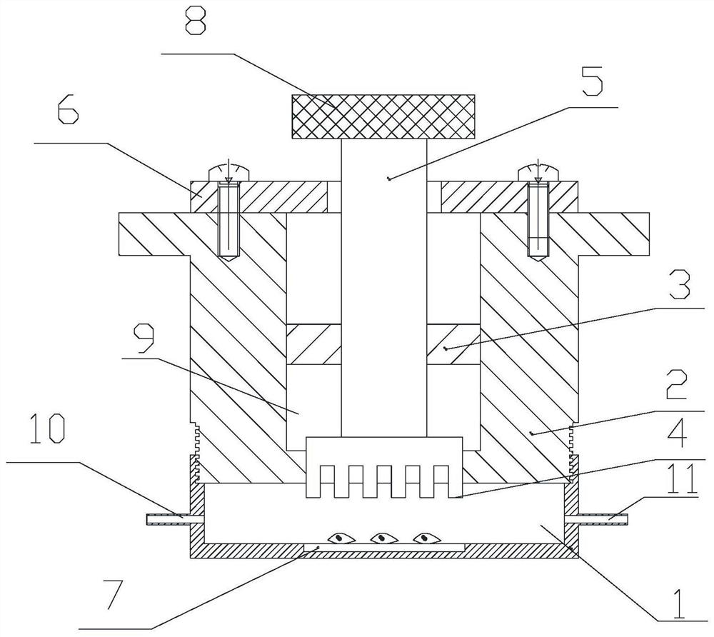
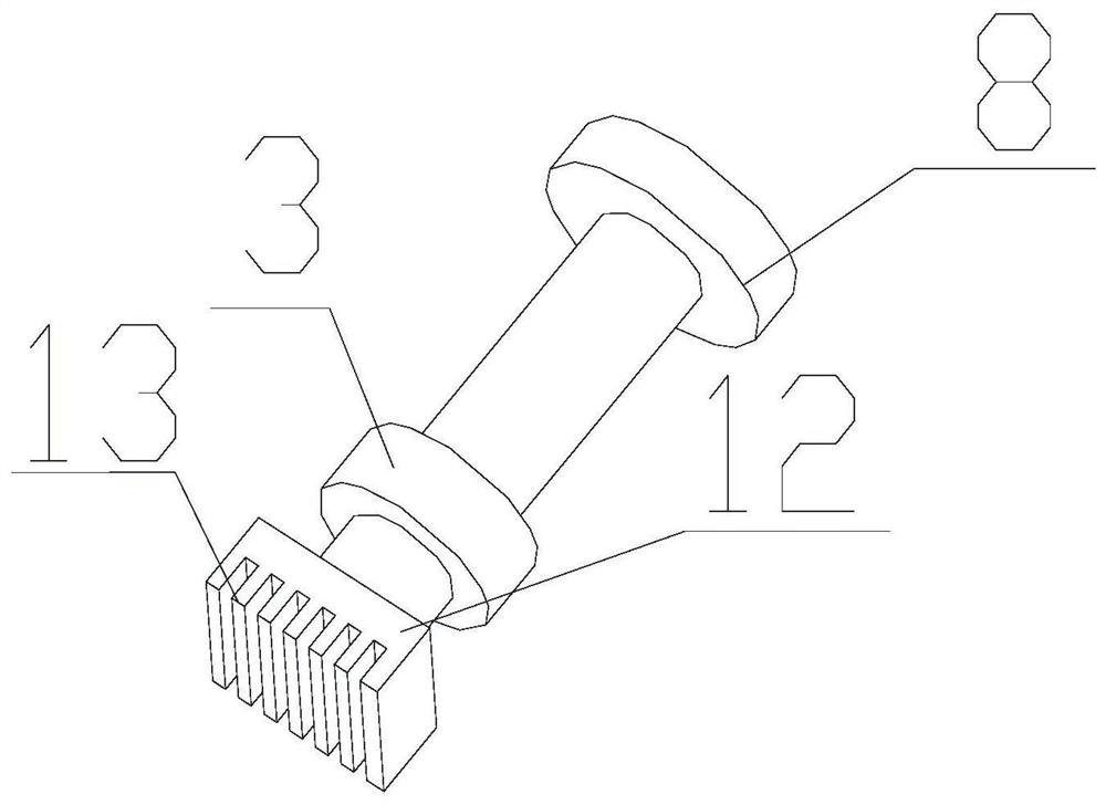
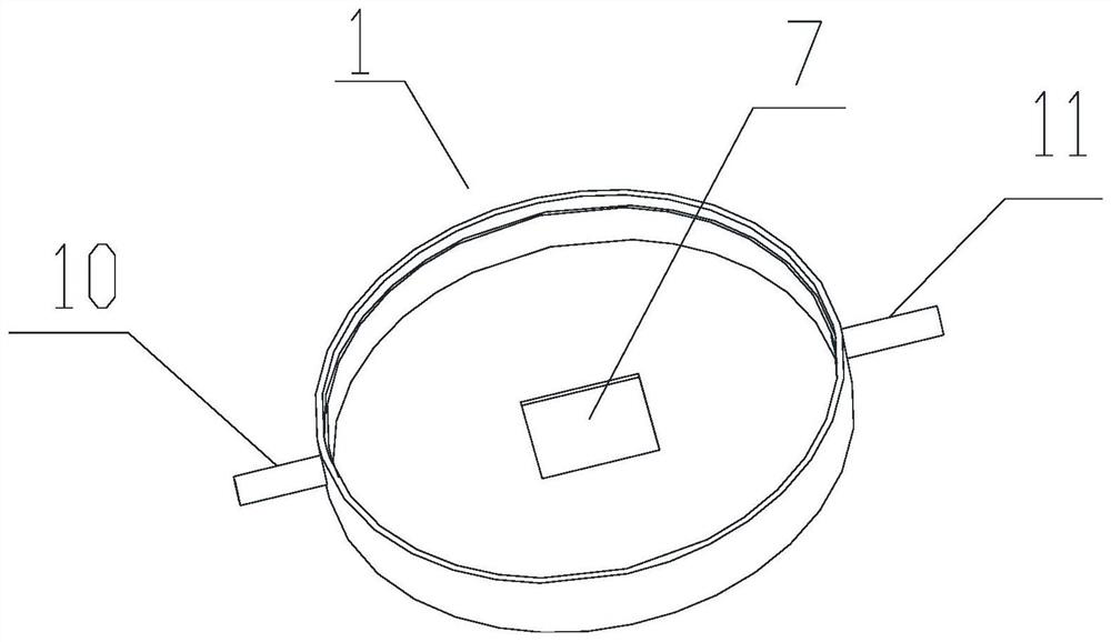
[0018] Such as figure 1 As shown, a flow chamber 1 for simulating the flow environment behind the support is characterized in that it includes an external screw 2, and the external screw 2 is provided with a sliding chamber 9, and a sliding rod 5 is provided for sliding in the sliding chamber 9. , one end of the slide bar 5 is provided with a bracket protrusion 4, the bracket protrusion 4 is made of stainless steel or magnesium alloy, the bracket protrusion 4 is composed of a number of bracket bars 13 and a base 12, and a number of the bracket bars 13 Evenly fixed on one end of the base body 12 , the other end of the base body 12 is fixed on the slide bar 12 . The bracket protrusion 4 exerts pressure on the liquid in the flow chamber 1 to simulate different liquid environments.

[0019] The end of the outer screw 2 close to the bracket protrusion 4 is connected to the shell of the flow chamber 1 through threads, the flow chamber 1 is made of transparent resin glass material, ...


PUM


Abstract

The present invention is a flow chamber for simulating the flow environment behind a support, which is characterized in that it includes an external screw rod, a sliding chamber is provided in the middle of the external screw rod, and a sliding rod is provided for rotation in the sliding chamber, and one end of the sliding rod There is a bracket protrusion, and the end of the outer screw rod close to the bracket protrusion is provided with a flow chamber, a groove is arranged in the middle of the flow chamber, a glass slide is arranged in the groove, and the slide bar passes through the A slide chamber is located within the flow chamber. The invention realizes the in vitro simulation of the blood flow environment after the stent is implanted in the blood vessel of the host, and provides the mechanical stimulation of the blood flow disturbance for the cultured cells at the bottom of the flow chamber. In this invention, the adjustable height of the lumen and the adjustable height of the stent wire protrusion make the flow chamber more flexible to simulate various mechanical environments after the stent is inserted into the host blood vessel; through the quantitative observation at the bottom of the flow chamber, it is relatively easy to culture cells in this mechanical environment. Real biological response, thus providing a new tool for studying adverse phenomena such as restenosis and thrombosis after stenting.

Description

technical field [0001] The invention relates to a flow chamber for simulating the flow environment behind a stent, which is a biomedical experimental device, in particular to a flow chamber for biological fluid experiments. Background technique [0002] Interventional stenting is a very common and highly effective treatment for occlusive atherosclerotic conditions. Although vascular stents have been greatly developed in terms of their configuration, materials, placement process, and postoperative antithrombotic drug therapy, the high incidence of postoperative intravascular restenosis and late thrombosis still affects the development of vascular stents. with its therapeutic effect. Studies have found that there is a close relationship between changes in the hemodynamic environment and the occurrence of adverse events (restenosis and thrombosis, etc.) during stenting. [0003] The flow chamber is a very effective tool to simulate the flow environment in vivo, but the existi...

Claims


Application Information

Patent Timeline
Patent Type & Authority Patents(China)
IPC IPC(8): C12M3/04
Inventor 范振敏杨钦焜叶霞张鹏
Owner JIANGSU UNIV OF TECH
Why Eureka
Try Eureka