Magnetic controllable reactor excitation current monitoring device and method based on Hall transformer

A magnetic control reactor and excitation current technology, applied in the direction of voltage/current isolation, transformer/inductor core, transformer/inductor coil/winding/connection, etc., can solve the problems of poor isolation and large volume, and achieve cost Inexpensive, high measurement accuracy, simple effect

Active Publication Date: 2019-05-03
杭州银湖电气设备有限公司
View PDF8 Cites 1 Cited by
  • Summary
  • Abstract
  • Description
  • Claims
  • Application Information

AI Technical Summary

Problems solved by technology

[0006] The technical problem to be solved by the present invention is: the technical problem of poor

Method used


Image

  • Magnetic controllable reactor excitation current monitoring device and method based on Hall transformer
  • Magnetic controllable reactor excitation current monitoring device and method based on Hall transformer
  • Magnetic controllable reactor excitation current monitoring device and method based on Hall transformer

Examples


Embodiment 1

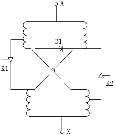
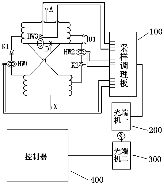
[0022] A magnetron reactor excitation current monitoring device based on Hall transformer, such as figure 2 As shown, it is a schematic structural diagram of the excitation current monitoring device of a magnetic control reactor in Embodiment 1. This embodiment is used in a magnetic control reactor. The magnetic control reactor includes an upper iron core, a lower iron core, a thyristor K1, a thyristor K2 and a diode D1. The upper iron core and the lower iron core are concentrically arranged opposite each other. The upper iron core is wound with an upper winding, and the lower iron core is wound with a lower winding. The head end of the upper winding is connected to the anode of the diode D1 and the head end of the lower winding. The terminal is connected to the cathode of diode D1 and the tail end of the lower winding. The upper winding and the lower winding have the same proportion of taps. The tap of the upper winding is connected to the anode of the thyristor K1. The catho...


PUM


Abstract

The invention relates to the technical field of a magnetic controllable reactor and particularly relates to a magnetic controllable reactor excitation current monitoring device and method based on a Hall transformer. The device includes a Hall sensor HW1, a Hall sensor HW2, a Hall sensor HW3, a sampling conditioning board, a first optical transceiver, a second optical transceiver and a controller,wherein the Hall sensor HW1 is mounted between a cathode of a thyristor K1 and a tail end of a lower winding, the Hall sensor HW2 is mounted between a cathode of a thyristor K2 and a tail end of an upper winding, the Hall sensor HW3 is mounted between a first end of the upper winding and an anode of a diode D1, the sampling conditioning board includes an adjustment filter circuit, and an output end of the adjustment filter circuit is connected with the controller through the first optical transceiver and the second optical transceiver. The device is advantaged in that a problem of secondary side current distortion caused by long-term magnetic biasing during ordinary electromagnetic current transformer CT measurement is avoided, a secondary circuit is easily isolated from the primary sidehigh voltage, and easy mounting, low cost and high measurement accuracy are realized.

Description

technical field [0001] The invention relates to the technical field of magnetron reactors, in particular to a Hall transformer-based magnetron reactor excitation current monitoring device and method. Background technique [0002] The full name of magnetically controlled reactors is magnetic valve controllable reactor, referred to as MCR, which is a shunt reactor with adjustable capacity, which is mainly used for reactive power compensation of high-voltage and ultra-high-voltage power systems. Compared with other types of SVC, magnetron-based MSVC has the advantages of small loss, small harmonics, fast response, high voltage resistance, high reliability, and low cost. The magnetic control reactor is composed of the control part and the reactor body, such as figure 1 As shown, it is a schematic diagram of the structure of a single-phase magnetically controlled reactor. The reactor is composed of upper and lower half core columns with windings of N / 2 symmetrically wound respec...

Claims


Application Information

Patent Timeline
IPC IPC(8): G01R19/25G01R15/20H01F27/24H01F27/28H01F27/29H01F27/40
Inventor 杨富文何建伟袁成邹俊峰韩宝锋杨圣利
Owner 杭州银湖电气设备有限公司
Why Eureka
Try Eureka