
Inflatable antenna with expandable space

A technology of inflatable antenna and space deployment, applied to inflatable antennas, antennas suitable for movable objects, antennas, etc., can solve the problems of uncontrollable filling volume and filling rate, poor stability and controllability of the deployment process, and low reliability of deployment, etc. problem, to achieve the effects of reducing the impact overload of deployment, increasing the effective area in an orderly manner, and improving safety and reliability

Active Publication Date: 2019-05-03
SPACETY CO LTD (CHANGSHA)
View PDF19 Cites 6 Cited by
  • Summary
  • Abstract
  • Description
  • Claims
  • Application Information

AI Technical Summary

Problems solved by technology

[0010] In the inflatable flexible antenna and its deployment method provided by this patent, because the deployment process depends on the deployment of the mechanical structure and its driving mechanism is complicated, the reliability of the deployment is low. Both the amount and the filling rate are uncontrollable, so there are many uncontrollable factors in the deployment process. At the same time, the uncontrollable deployment process and the impact of the launch impact force during the satellite launch will cause obvious shock and vibration in the overall structure, and the anti-interference The ability is poor, although the storage ratio is improved, the stability and controllability of the unfolding process is poor

Method used


Image

  • Inflatable antenna with expandable space
  • Inflatable antenna with expandable space
  • Inflatable antenna with expandable space

Examples


Embodiment Construction

[0041] The present invention will be described in detail below in conjunction with the accompanying drawings.

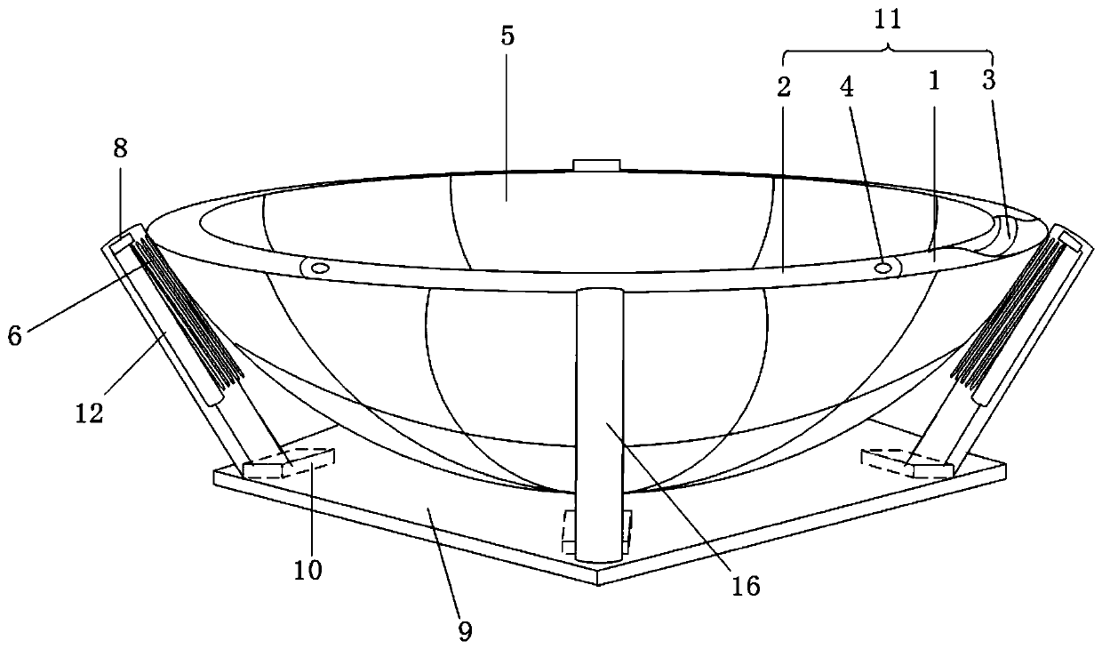
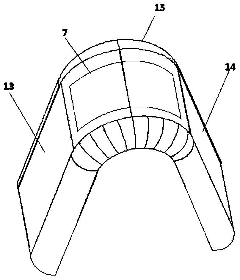
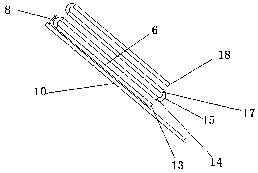
[0042] The first-stage deployment assembly 11 at least includes a first inflatable support ring 1 and a second inflatable support ring 2 whose shapes are defined by arcs and have hollow inner chambers. The first inflatable support ring 1 and the second inflatable support ring 2 can be nested and connected to each other, so that the first antenna folded surface 5 can be compressed and folded in height and radial direction, so as to reduce the occupied volume of the first antenna folded surface 5 .

[0043] Preferably, the first inflatable support ring 1 and the second inflatable support ring 2 are arranged adjacent to and spaced apart from each other along the circumferential direction in such a manner that the centers of the two are located at the same point. Preferably, there are two first inflatable support rings 1 and two second inflatable support rings 2, both si...


PUM


Abstract

The invention relates to an inflatable antenna with an expandable space. The inflatable antenna at least comprises a flexible antenna folding surface and an unfolding assembly. The unfolding assemblyis composed of at least two stages of unfolding assemblies which can be sequentially driven by taking the inflation pressure as the driving force thereof and respectively connected to different heights on the folding surface of the flexible antenna. The first stage of unfolding assembly can expand outwards under the driving effect of taking the inflation pressure as the driving force applied to the first stage of unfolding assembly so as to drive at least one part of the folding surface of the flexible antenna to unfold. When the first stage of unfolding assembly is expanded to a first-stage complete unfolding position, the second stage of unfolding assembly expands in a graded manner in such a way that the shape memory effect of a shape memory material plate positioned on the folding surface of the flexible antenna is released under the effect of the driving force applied to the second stage of unfolding assembly. In this way, the folding surface of the flexible antenna is controllably unfolded in an incomplete or complete space manner in a graded manner from bottom to top in a manner of increasing the effective unfolding area and reducing the unfolding impact overload.

Description

technical field [0001] The invention relates to the fields of aerospace technology and antenna technology, in particular to a space expandable inflatable antenna. Background technique [0002] The issue of antenna deployability is especially important as the size of satellites becomes smaller. While the sensors and operating electronics of miniaturized satellites can be scaled to extremely small volumes, the wavelengths of the signals used by such miniaturized satellites for communication do not scale accordingly. Given that the wavelength of a signal determines the size of the antenna used to transmit that signal, antennas for miniaturized satellites are still of similar size to larger satellites. Geostationary orbit satellites and deep space exploration activities require long-distance communication measurement and control, so it is very important to ensure that the receiving end has a large signal power, and the only way to ensure that the receiving end has a large signa...

Claims


Application Information

Patent Timeline
IPC IPC(8): H01Q1/08H01Q1/28
CPCH01Q1/08H01Q1/081H01Q1/288
Inventor 杜志贵杨峰任维佳向晓霞
Owner SPACETY CO LTD (CHANGSHA)
Learn More