
Sliding type lathe

A sliding, lathe technology, applied in turning equipment, turning equipment, metal processing equipment, etc., can solve the problems of low production efficiency of lathes, and achieve the effects of light movement, low friction resistance, and low wear

Inactive Publication Date: 2019-05-07
新昌县北斗压缩机有限公司
View PDF0 Cites 0 Cited by
  • Summary
  • Abstract
  • Description
  • Claims
  • Application Information

AI Technical Summary

Problems solved by technology

This kind of lathe has low production efficiency and is suitable for single piece and small batch production

Method used


Image

  • Sliding type lathe

Examples


Embodiment Construction

[0018] The technical solutions in the embodiments of the invention will be clearly and completely described below in conjunction with the accompanying drawings in the embodiments of the invention. Obviously, the described embodiments are only part of the embodiments of the invention, not all of them. example. Based on the embodiments of the present invention, all other embodiments obtained by persons of ordinary skill in the art without making creative efforts belong to the protection scope of the present invention.

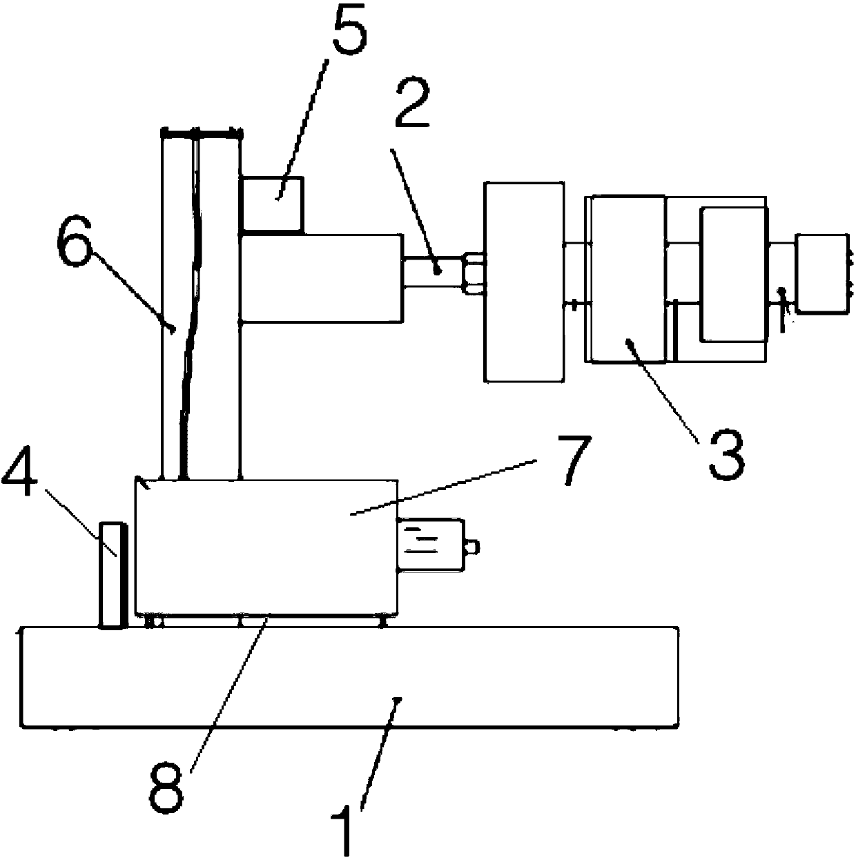
[0019] A sliding lathe, comprising a sliding base 1, a connecting shaft 2, a sleeve 3, a positioning plate 4, a lateral moving part 5, a longitudinal moving part 6 and a fastener 7; the sliding base 1 is connected to the sleeve through a connecting shaft The sleeve; the sleeve is provided with mounting holes through the front and rear; the sliding base is provided with a rolling linear slide rail and a rolling body; the rolling body is built in the groove of the ...


PUM


Abstract

The invention provides a sliding type lathe comprising a sliding base, a connecting shaft, a sleeve, a positioning plate, a lateral moving member, a longitudinal moving member and a fastener. The sliding base is connected to the sleeve through the connecting shaft, the sleeve is provided with an installation hole penetrating front and rear, the sliding base is provided with a rolling linear sliding rail and a rolling body, the rolling body is built in a groove of the rolling linear sliding rail, and the positioning plate is firmly mounted between the lateral moving member and the longitudinalmoving member through the fastener. The sliding type lathe is high in positioning precision, small in frictional resistance, thus stable in movement, not likely to slide when moving at a low speed, convenient to move, small in abrasion, good in precision keeping, capable of machining large-diameter deep holes, high in machining precision and good in using effect.

Description

technical field [0001] The invention belongs to the field of mechanical technology processing, and in particular relates to a sliding lathe. Background technique [0002] Lathe is an important object in mechanical processing, which plays a decisive role in daily life and work production; with the market development of CNC heavy-duty horizontal lathe, it is often necessary to process shaft workpieces with a length of more than 10 meters, and the effective moving distance of the tool holder is larger , and with the extension of the length of the workpiece; the traditional lathe is driven by hand or pedal, the workpiece is rotated through the rope, and the tool is hand-held for cutting; the current lathe is a lathe with a gear box driven by a separate motor; the spindle The speed and feed can be adjusted in a large range, and can process the internal and external surfaces, end surfaces and internal and external threads of the workpiece. This kind of lathe has low production ef...

Claims


Application Information

Patent Timeline
Patent Type & Authority Applications(China)
IPC IPC(8): B23B3/06
Inventor 熊春生
Owner 新昌县北斗压缩机有限公司
Learn More