
Laser processing apparatus and method, laser packaging method, laser annealing method

A laser processing and laser technology, which is applied in the fields of laser annealing, laser packaging method, and laser processing device, can solve the problems of increasing yield, not reaching the optimum effect, and increasing cost, so as to improve yield, reduce cost, and improve efficiency effect

Active Publication Date: 2021-03-09
SHANGHAI MICRO ELECTRONICS EQUIP (GRP) CO LTD
View PDF3 Cites 0 Cited by
  • Summary
  • Abstract
  • Description
  • Claims
  • Application Information

AI Technical Summary

Problems solved by technology

The former uses a single galvanometer scanning device, which must require the lens of the galvanometer to be large enough to realize the control of the optical path. If multi-channel packaging is realized, there are special requirements for the lens on the galvanometer of the scanning device, which increases the need for the galvanometer. Accuracy requirements and rotation speed requirements, in order to achieve synchronous packaging of multi-beam optical paths, there are limitations to the requirements of the galvanometer; the latter adds a scanning device, which splits the light after the optical fiber of the light source emits light, and divides the optical path into multiple paths through the reflector , using multiple scanning equipment for packaging, the requirements for scanning equipment are similar to the general packaging marking method, which improves the packaging effect, but increases the cost of a laser scanning equipment, and the effect is not optimal
[0005] The above-mentioned schemes have greatly improved the yield, but for the existing schemes, they all optimize the yield at the expense of cost, and have not really achieved both cost savings and increased yield

Method used


Image

  • Laser processing apparatus and method, laser packaging method, laser annealing method
  • Laser processing apparatus and method, laser packaging method, laser annealing method
  • Laser processing apparatus and method, laser packaging method, laser annealing method

Examples


Embodiment 2

[0076] The difference between this embodiment and Embodiment 1 is that please refer to Figure 8 , in order to achieve no dead angle in the scanning process, two reflectors can be arranged on both sides of the beam splitter 220, which are respectively the second reflector 230 and the third reflector 240 on the left side, the second reflector 230 and the third reflector 240 The beam splitter 220 is symmetrical, and the height of the two reflecting mirrors relative to the material to be processed is smaller than the height of the beam splitter 220 relative to the material to be processed.

[0077] The reflected light and refracted light split by the beam splitter 220 are respectively reflected by the second reflector 230 and the third reflector 240 into the lens module. At this time, the beam splitter 220 and the two reflectors are all perpendicular to the lens module. The processing rate and processing path of refracted light are the same.

[0078] Please refer to Figure 9 a...

Embodiment 3

[0080] The difference between this embodiment and the first embodiment is that please refer to Figure 14 and Figure 15 :

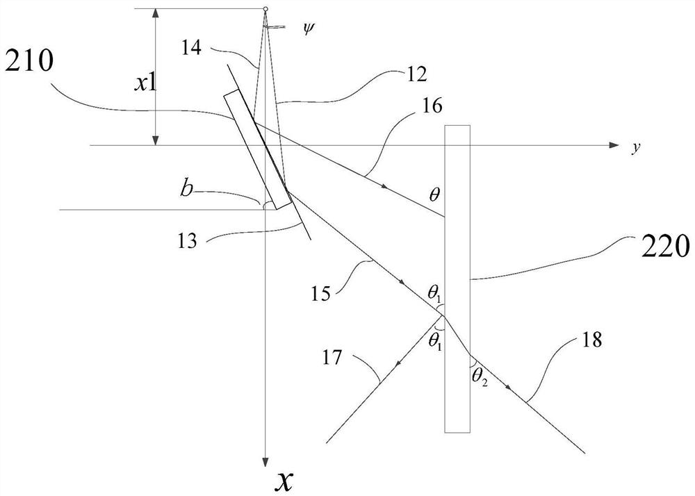
[0081] Please refer to Figure 11 , at this time, it is also necessary to set two reflectors, and the two reflectors are also placed vertically, but the heights of the two reflectors relative to the material to be processed are not equal. In addition, the beam splitter 220 is placed obliquely, and the angle between it and the horizontal plane is α.

[0082] Figure 11 In the laser beam incident to the beam splitter 220, two edge rays with the largest spacing are selected, which are respectively 21 and 22, and when they are incident on the beam splitter 220, two incident points are generated, which are point A and point B respectively, and are projected to point A The light above is reflected by the beam splitter 220 to form a reflected light 23, and the light projected on point B is reflected by the beam splitter 220 to form a reflected light 24, wher...


PUM


Abstract

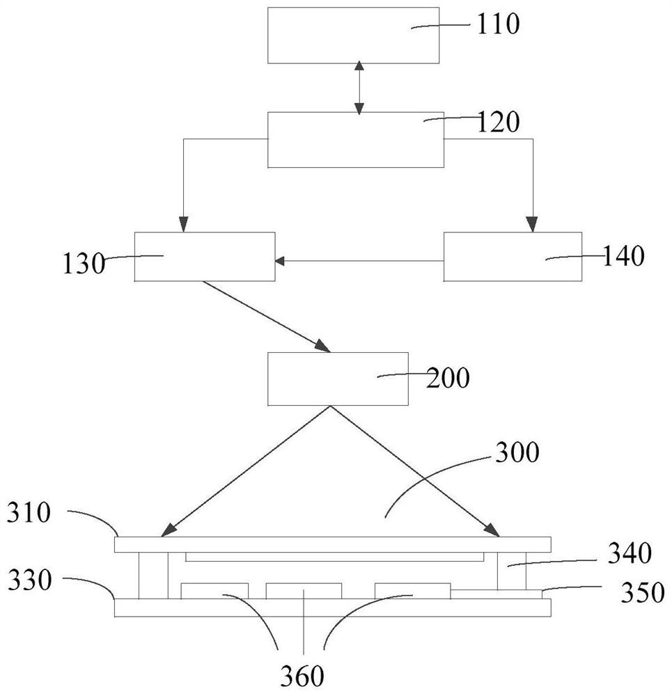
The present invention provides a laser processing device and method, a laser packaging method, and a laser annealing method. A laser processing device includes a laser module, a laser scanning module, a light splitting module and a control unit, and the laser module provides laser light for processing, The laser passes through the laser scanning module and then enters the spectroscopic module, and the spectroscopic module splits the laser light to form reflected light and refracted light, and the laser scanning module controls the reflected light and the refracted light to follow. The scanning path scans the material to be processed symmetrically; the control unit is connected to the laser module and the laser scanning module for controlling the laser module and the laser scanning module. The invention adopts the light splitting module to split light, the utilization rate of the laser module is more than 2 times that of the prior art, the requirement for the rotation angle of the equipment is reduced by 2 times or more compared with the prior art, and the yield is increased by more than 2 times.

Description

technical field [0001] The invention relates to the field of laser processing, in particular to a laser processing device and method, a laser packaging method, and a laser annealing method. Background technique [0002] The existing laser encapsulation process provides a laser beam, sets the material to be packaged on the workpiece table, and the laser beam passes through a related shaping device and irradiates the material to be packaged, so that the glass frit on the material to be packaged is melted and condensed to complete the package. [0003] In order to improve the productivity and the speed of processing products, the light path is split in the shaping device, so that a set of laser packaging devices can package several materials to be packaged at the same time. Such as Chinese patent CN201410603985.7 (disclosure date: June 11, 2016), CN201010180148.X (disclosure date: November 23, 2011), CN201020235578.2 (disclosure date: March 2, 2011) all disclosed The process o...

Claims


Application Information

Patent Timeline
Patent Type & Authority Patents(China)
IPC IPC(8): B23K26/064B23K26/082B23K26/067H01L21/67
Inventor 唐江锋刘志宇
Owner SHANGHAI MICRO ELECTRONICS EQUIP (GRP) CO LTD
Learn More