
An obstacle avoidance detection device for power inspection UAV

A detection device and power inspection technology, applied in the field of obstacle avoidance detection, can solve problems such as the decrease in detection accuracy of millimeter-wave radar, inconvenient storage and transportation of drones, interference from millimeter-wave radar echoes, etc., to achieve convenient storage and transportation , Eliminate radar false alarms and false alarms, and improve the effect of detection angle

Active Publication Date: 2020-10-16
成都优艾维智能科技有限责任公司
View PDF8 Cites 0 Cited by
  • Summary
  • Abstract
  • Description
  • Claims
  • Application Information

AI Technical Summary

Problems solved by technology

[0005] For the existing UAV radar obstacle avoidance system, first, most of its millimeter-wave radars are installed vertically. When the aircraft is flying, due to the rotation of the propeller, it will cause certain interference to the echo of the millimeter-wave radar. As a result, the detection accuracy of millimeter-wave radar decreases
Second, the radar obstacle avoidance system of most UAVs is fixed under the fuselage, and the landing gear and other structural parts will block part of the beam emitted by the radar, resulting in false radar or false report of obstacles
Third, the radar obstacle avoidance system of most drones is fixed on the fuselage with screws, which is cumbersome to disassemble and assemble, which will make the storage and transportation of drones extremely inconvenient

Method used


Image

  • An obstacle avoidance detection device for power inspection UAV
  • An obstacle avoidance detection device for power inspection UAV
  • An obstacle avoidance detection device for power inspection UAV

Examples


Embodiment Construction

[0025] The technical solution of the present invention will be further described in detail below in conjunction with the accompanying drawings, but the protection scope of the present invention is not limited to the following description.

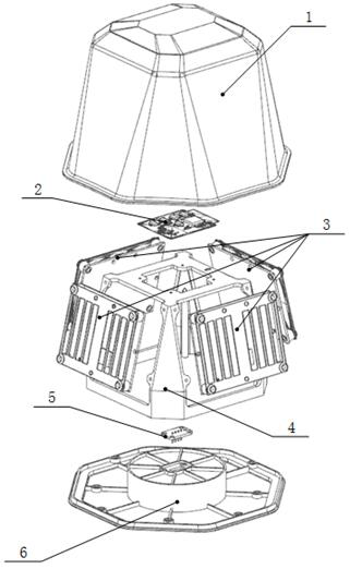
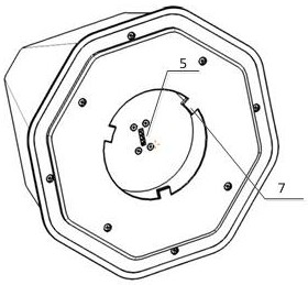
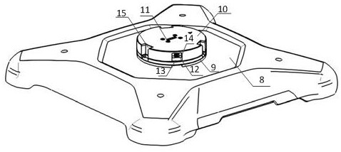
[0026] Such as Figure 1~2 As shown, an obstacle avoidance detection device for electric power inspection UAV includes a radar detection module and a connection structure arranged on the top cover of the UAV; the radar detection module communicates with the UAV through the connection structure on the top cover Fix the man-machine;

[0027] The radar detection module includes a radar bottom cover 6, a first probe connector 5 and a radar mounting bracket 4; the bottom of the radar mounting bracket 4 is fixed on the upper surface of the radar bottom cover 6, and the top of the radar mounting bracket 4 A millimeter-wave conversion board 2 is provided, and millimeter-wave radar detectors 3 in four directions of front, rear, left and right are i...


PUM


Abstract

The invention discloses an obstacle avoidance detecting device for an electric power inspection unmanned aerial vehicle, comprising a radar detection module and a connecting structure provided on thetop cover of the unmanned aerial vehicle. The radar detection module is fixed to the unmanned aerial vehicle by the connecting structure on the top cover of the unmanned aerial vehicle. The radar detection module comprises a radar bottom cover (6), a first probe connector (5) and a radar mounting bracket (4). A probe mounting groove is formed in the center of the upper surface of the radar bottomcover (6). The first probe connector (5) is provided in the probe mounting groove and penetrates through the lower surface of the radar bottom cover (6). A plurality of protruding claws (7) located around the first probe connector (5) are provided on the lower surface of the radar bottom cover (6). The first probe connector (5) is electrically connected to the millimeter wave conversion board (2).According to the obstacle avoidance detecting device for an electric power inspection unmanned aerial vehicle, the propellers of the obstacle avoidance detecting device interfering the radar echoes due to vertical mounting, and the detection precision of the obstacle avoidance detecting device is greatly improved.

Description

technical field [0001] The invention relates to obstacle avoidance detection, in particular to an obstacle avoidance detection device used for electric power inspection drones. Background technique [0002] In the traditional UAV power inspection application, the UAV is manually controlled throughout the entire process. The UAV cannot cause damage to the line during the inspection process, and needs to maintain a certain clearance distance from the inspection line. Due to the error of the viewing angle, it is difficult for the inspectors to judge whether the distance between the UAV and the transmission line meets the requirements during the operation. In order to ensure the quality of the inspection results and the safety of the operation, the inspectors need to be highly focused. It is difficult to ensure the safety of the operation. At this time, distance measuring equipment is needed to help the inspectors judge the distance and estimate the risk. [0003] With the deve...

Claims


Application Information

Patent Timeline
Patent Type & Authority Patents(China)
IPC IPC(8): G01S13/935
Inventor 赵云杰陈龙邱胜蓝
Owner 成都优艾维智能科技有限责任公司
Learn More