
Injection system of a natural gas hydrate development simulation experiment device

A technology for simulating experimental devices and injection systems, which is applied in the field of injection systems of simulating experimental devices for the development of natural gas hydrates, and can solve problems such as obvious differences, unscientific, and limited scope of application of models

Active Publication Date: 2020-10-27
OIL & GAS SURVEY CGS
View PDF5 Cites 0 Cited by
  • Summary
  • Abstract
  • Description
  • Claims
  • Application Information

AI Technical Summary

Problems solved by technology

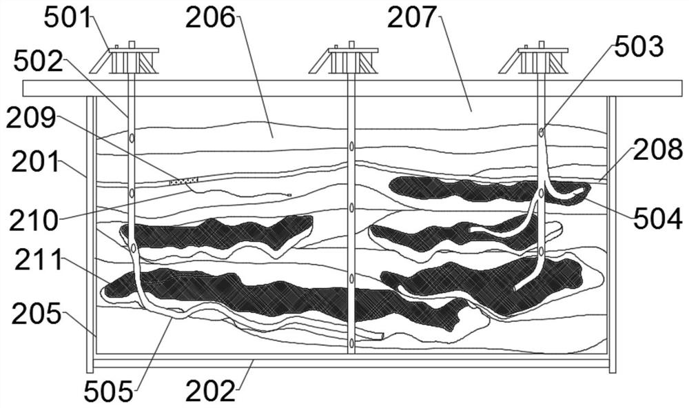
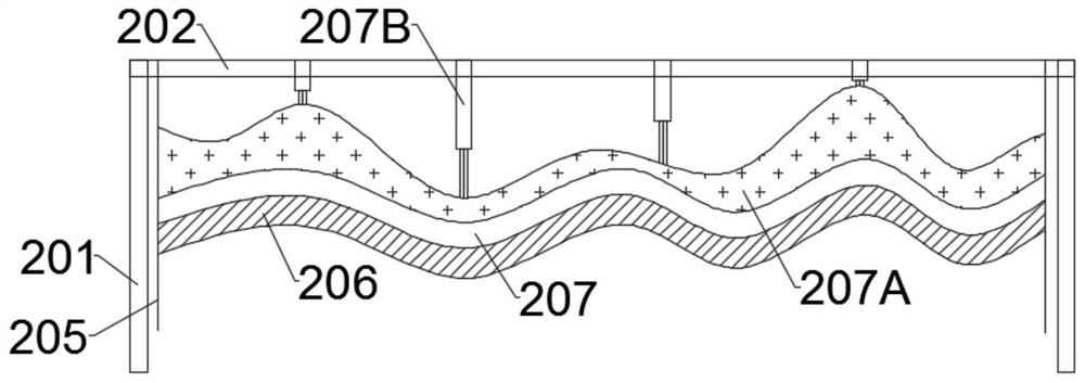
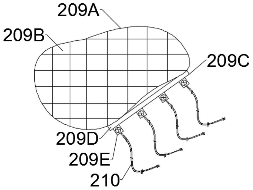
[0008] (1) Existing simulation devices cannot construct specific stratum structures based on actual geological data, or simulate the actual environment through stratum structures. Because this process is difficult to simulate effectively, the simulation effect is different from the actual results. Inconsistencies or obvious differences lead to simulation results that cannot be directly used to guide actual production, but can only be used as an auxiliary basis for theoretical guidance;
[0009] (2) Existing simulation devices are often closed, and the simulated conditions are limited to the model body, and all its parameters and simulation conditions cannot be combined to form a dynamic equilibrium, which cannot simulate hydrate The dynamic environment, especially in the process of mining, the environment in which it is located is in the process of establishing balance and destroying balance, so it is impossible to simulate the dynamic mining process;
[0010] (3) In the existing simulation device, there is a fixed structure between the model body and the base, but this fixed structure limits the scope of application of the model, that is, for a model, what is preset to simulate Well patterns of different types can only simulate this type and cannot exceed this range, which is obviously unscientific

Method used


Image

  • Injection system of a natural gas hydrate development simulation experiment device
  • Injection system of a natural gas hydrate development simulation experiment device
  • Injection system of a natural gas hydrate development simulation experiment device

Examples


Embodiment Construction

[0056] The following will clearly and completely describe the technical solutions in the embodiments of the present invention with reference to the accompanying drawings in the embodiments of the present invention. Obviously, the described embodiments are only some, not all, embodiments of the present invention. Based on the embodiments of the present invention, all other embodiments obtained by persons of ordinary skill in the art without making creative efforts belong to the protection scope of the present invention.

[0057] Such as figure 1 As shown, the present invention provides a natural gas hydrate development simulation experiment device, including a three-dimensional model system and a one-dimensional long pipe simulation system independent of each other, wherein the three-dimensional model system is composed of a model body and a rotating mechanism, and the model body is set There is an injection system, which is divided into a formation pressure injection system in...


PUM


Abstract

The invention discloses an injection system of a development simulation experiment device for natural gas hydrate. The system comprises a simulation formation pressure injection system and a displacement pressure injection system. The simulation formation pressure injection system is connected with a liquid filling and pressurizing transferring device through an output pipe. The displacement pressure injection system is directly arranged on an injection-production base. The simulation formation pressure injection system comprises a balanced high-pressure generation chamber and a balanced pressure boost pump. A gas inlet pipe of the balanced pressure boost pump is connected with a power extraction mechanism. An outlet pipe of the balanced pressure boost pump is connected with a plurality ofconveying pipelines and is provided with a primary pressure measuring meter. A secondary pressurizing pump connected with a conveying pipe is connected to each conveying pipeline. A flow control regulation valve, a balance injection gas pressure gauge, and a switch valve are arranged between an outlet pipe of the secondary pressurizing pump and the conveying pipe. The injection system of the development simulation experiment device for the natural gas hydrate can continuously change the pressure of the simulation high-pressure equilibrium conditions, improve the control range of the simulation, and expand balanced and stable high-pressure range when simulating natural gas hydrate.

Description

technical field [0001] The invention relates to the technical field of hydrate simulation devices, in particular to an injection system of a natural gas hydrate development simulation experiment device. Background technique [0002] Considerable reserves promote the continuous progress of development technology, and technological innovation will drive the efficient development of reserves. Since this century, the whole world has recognized that natural gas hydrate is a clean energy alternative to conventional fossil fuels. More than 200 hydrate deposits have been discovered in the world. Based on the current energy consumption trend, only 15% of hydrate mining can be used globally for 200 years. However, the stable temperature and pressure conditions formed by itself determine the particularity of its mining method. In addition, the impact of its mining process on the environment needs further evaluation. Therefore, most of the current research on hydrate mining is still i...

Claims


Application Information

Patent Timeline
Patent Type & Authority Patents(China)
IPC IPC(8): G01V1/40G01V1/30
Inventor 张帅陈兆凤张建华陆程祝有海庞守吉肖睿
Owner OIL & GAS SURVEY CGS
Learn More