Terminal antenna used in wireless local area network

A wireless local area network and terminal antenna technology, applied in the direction of antenna, antenna grounding device, antenna support/installation device, etc., can solve the problems of insufficient bandwidth, difficult debugging, poor product effect, etc., and achieve the effect of increasing bandwidth

Active Publication Date: 2019-05-07
GUANGZHOU CREKING COMM TECH
View PDF6 Cites 6 Cited by
  • Summary
  • Abstract
  • Description
  • Claims
  • Application Information

AI Technical Summary

Problems solved by technology

[0002] In the network coverage of wireless local area network (English name is Wireless Local Area Networks, abbreviated as WLAN), in order to meet the requirements of smaller antenna size and prevent the interference of other electromagnetic waves, while covering multiple communication frequency bands, dual-band and multi-band antennas Emerged as the times require; the existing wireless LAN terminal antennas, especially the terminal antennas that are matched with machine equipment, have the problems of large antenna size, high cost, and not suitable for mass production, and interference between the two antennas is easy, debugging Difficult, the effect of the product is poor; a small number of terminal antennas that are matched with the machine equipment have not solved the problems of low standing wave, high gain and good directivity, and there are problems such as insufficient bandwidth and poor radiation performance indicators. It is difficult to meet the application of wireless LAN terminal equipment in wireless network coverage

Method used


Image

  • Terminal antenna used in wireless local area network
  • Terminal antenna used in wireless local area network
  • Terminal antenna used in wireless local area network

Examples


Embodiment Construction

[0036] The following will clearly and completely describe the technical solutions in the embodiments of the present invention with reference to the accompanying drawings in the embodiments of the present invention. Obviously, the described embodiments are only some, not all, embodiments of the present invention. Based on the embodiments of the present invention, all other embodiments obtained by persons of ordinary skill in the art without making creative efforts belong to the protection scope of the present invention.

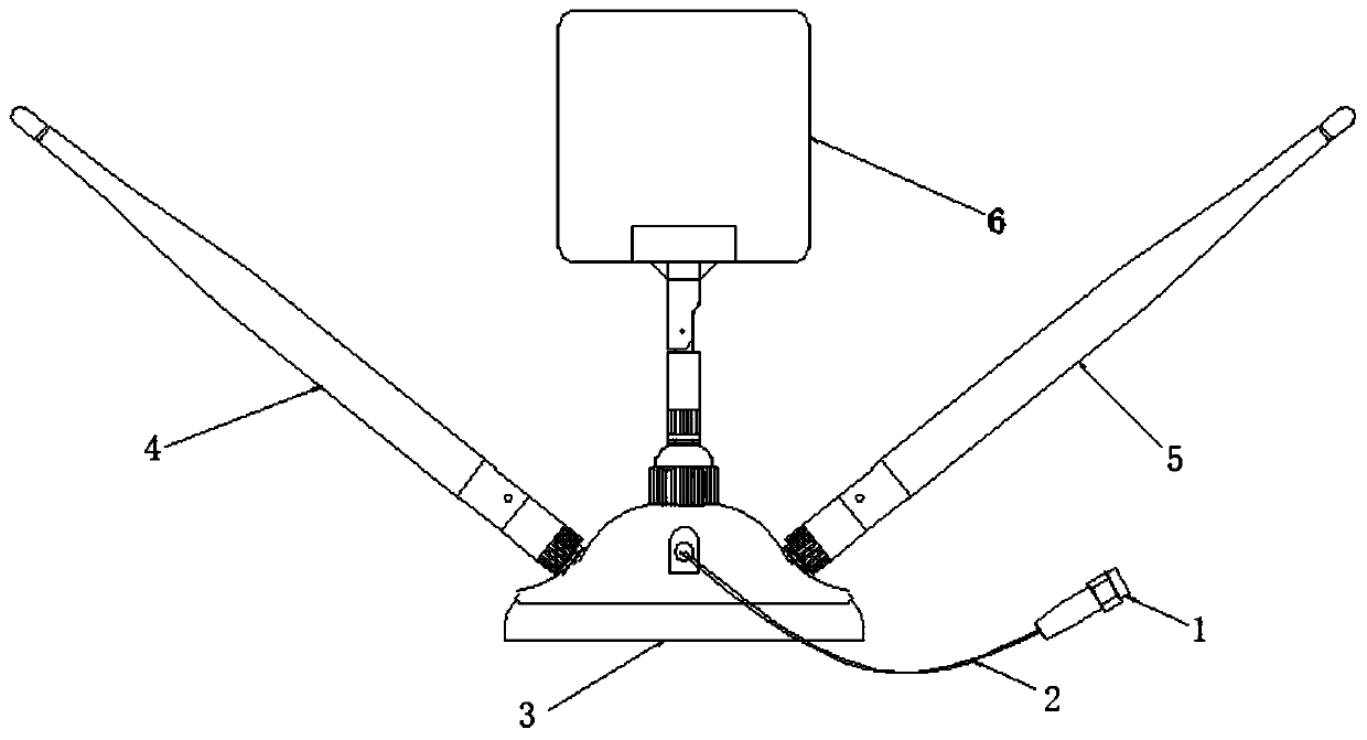
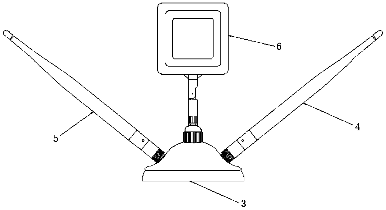
[0037] In the embodiment of the present invention applied to the terminal antenna of the wireless local area network, the front structural diagram of the terminal antenna applied to the wireless local area network is as follows figure 1 As shown, the structure diagram of the back of the terminal antenna of the application in the wireless LAN is as follows figure 2 As shown, in this embodiment, the terminal antenna applied to the wireless local area network in...


PUM


Abstract

The invention discloses a terminal antenna used in a wireless local area network. The terminal antenna comprises a radio frequency connector, a feeding cable, a suction cup base, a 2.4G band antenna,a 5G band antenna and a combiner. The left side of the suction cup base is provided with a mounting screw and is fixedly installed with the 2.4G band antenna, the right side of the suction cup base isprovided with a mounting screw and is fixedly installed with the 5G band antenna, the top portion of the suction cup base is provided with a mounting screw and is fixedly installed with the combiner,the combiner is internally provided with a frequency division unit circuit board, the frequency division unit circuit board is provided with a 2.4G band feed connection, a 2.4G band grounding connection, a 5G band feed connection and a 5G band grounding connection, and the 2.4G band antenna and the 5G band antenna are welded and fixed with the output end of the frequency division unit circuit board through respective connection cables. The volume is small, the weight is light, the anti-interference ability is strong, the frequency band is wide, the gain is high, and the radiation performanceindex is good.

Description

technical field [0001] The invention relates to the field of antennas, in particular to a terminal antenna applied in a wireless local area network. Background technique [0002] In the network coverage of wireless local area network (English name is Wireless Local Area Networks, abbreviated as WLAN), in order to meet the requirements of smaller antenna size and prevent the interference of other electromagnetic waves, while covering multiple communication frequency bands, dual-band and multi-band antennas Emerged as the times require; the existing wireless LAN terminal antennas, especially the terminal antennas that are matched with machine equipment, have the problems of large antenna size, high cost, and not suitable for mass production, and interference between the two antennas is easy, debugging Difficult, the effect of the product is poor; a small number of terminal antennas that are matched with the machine equipment have not solved the problems of low standing wave, h...

Claims


Application Information

Patent Timeline
Patent Type & Authority Applications(China)
IPC IPC(8): H01Q1/36H01Q1/48H01Q1/50H01Q1/24H01Q5/10H01Q5/20H01Q5/30H01Q5/307H01Q5/50
Inventor 唐江华许佐云
Owner GUANGZHOU CREKING COMM TECH
Why Eureka
Try Eureka