Check patentability & draft patents in minutes with Patsnap Eureka AI!

Polymer devolatilization device

A devolatilization device, polymer technology, applied in vertical tube evaporators, evaporator accessories, evaporation, etc., can solve the problems of reduced polymer yield, high volatile vapor velocity, vapor phase pipeline blockage, etc., and achieve short heating time. , The effect of reducing entrainment and preventing scaling

Pending Publication Date: 2019-05-10
上海宥壹化工科技有限公司
View PDF0 Cites 3 Cited by
  • Summary
  • Abstract
  • Description
  • Claims
  • Application Information

AI Technical Summary

Problems solved by technology

At the same time, the existing partial devolatilization device entrains more polymer materials in the liquid phase when the volatile gas is discharged, resulting in a decrease in polymer yield, or when dealing with polymer solutions with high volatile content, the volatile The vapor velocity is high, and the volatile gas entrains the liquid phase polymer into the vapor phase outlet pipe, causing blockage of the vapor phase pipe

Method used


Image

  • Polymer devolatilization device
  • Polymer devolatilization device
  • Polymer devolatilization device

Examples


Embodiment 1

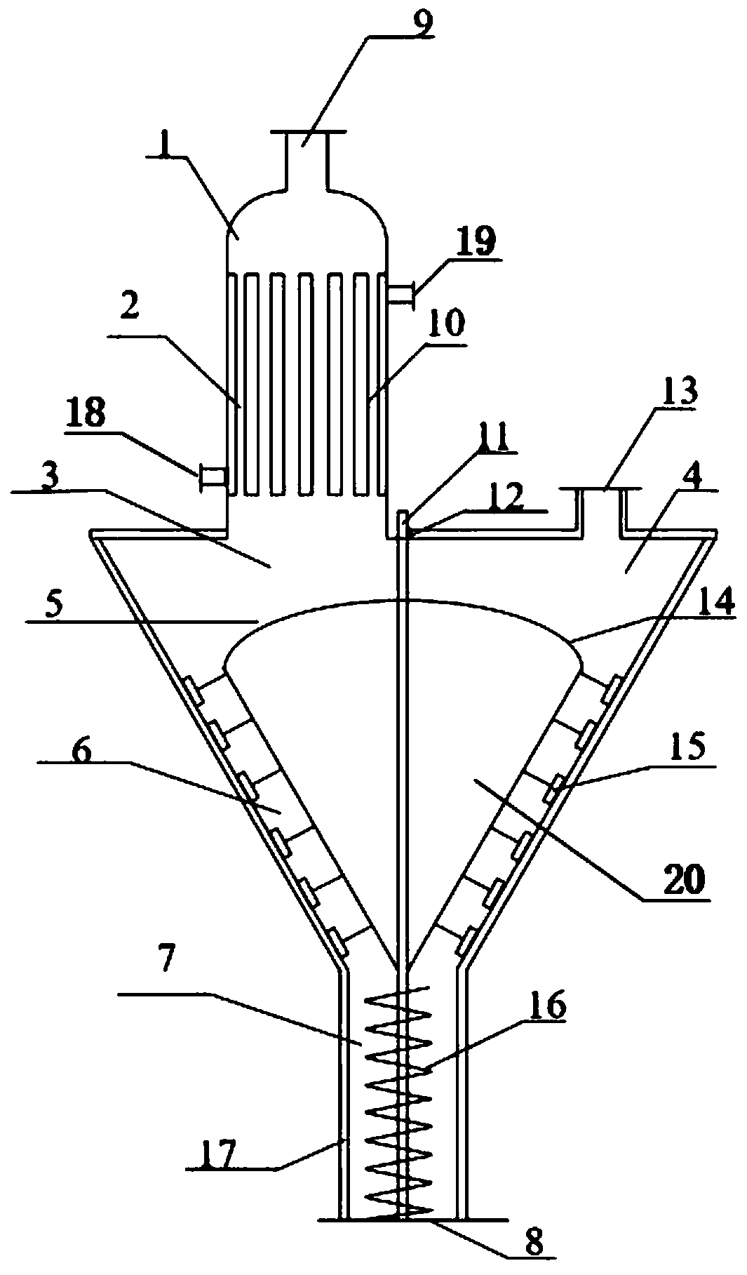
[0035] See attached figure 1 , is a structural schematic diagram of a polymer devolatilization device in an embodiment of the present invention, and the devolatilization device is provided with: a feed distribution area 1, a heating devolatilization area 2, a strip devolatilization area 3, and a vapor phase collection and discharge area 4 , Falling film devolatilization zone 5, bubble breaking devolatilization zone 6 and material collection zone 7.

[0036] The feed distribution area 1 is provided with a feed inlet 9, and the feed inlet 9 is arranged on the top or side of the feed distribution area 1, and the polymer enters the devolatilization from the feed inlet 9. device. In this embodiment, the feed inlet 9 is arranged at the top of the feed distribution area 1 .

[0037] The heating devolatilization zone 2 is located below the feed distribution zone 1, and the heating devolatilization zone 2 is provided with a heating device, which is used to heat the polymer to the tem...

Embodiment 2

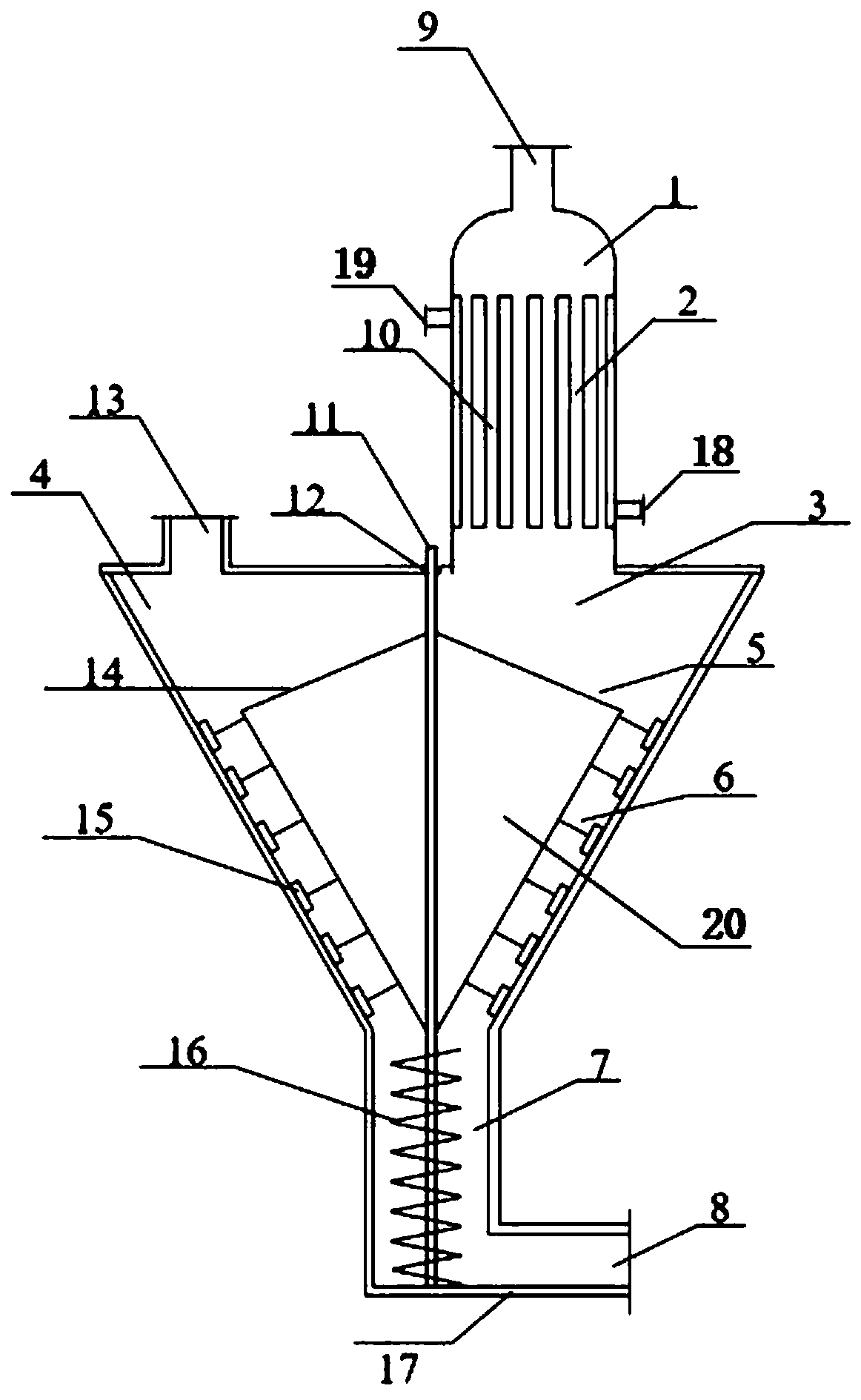
[0045] See attached figure 2, is a structural schematic diagram of a polymer devolatilization device in another embodiment of the present invention, and the devolatilization device is provided with: a feed distribution area 1, a heating devolatilization area 2, a strip devolatilization area 3, and a vapor phase collection and discharge area 4. Falling film devolatilization zone 5, bubble breaking devolatilization zone 6 and material collection zone 7.

[0046] The feed distribution area 1 is provided with a feed inlet 9, and the feed inlet 9 is arranged on the top or side of the feed distribution area 1, and the polymer enters the devolatilization from the feed inlet 9. device. In this embodiment, the feed inlet 9 is arranged at the top of the feed distribution area 1 .

[0047] The heating devolatilization zone 2 is located below the feed distribution zone 1, and the heating devolatilization zone 2 is provided with a shell-and-tube heat exchanger, and the tube layer of the...


PUM


Abstract

The invention provides a polymer devolatilization device, which comprises a feeding distribution area, a heating devolatilization area, a falling strip devolatilization area, a vapor-phase collectionand removal area, a falling film devolatilization area and a material collection area. The feeding distribution area is provided with a feeding port; the heating devolatilization area is positioned below the feeding distribution area and provided with a heating device for heating a polymer to a devolatilization temperature; the falling strip devolatilization area is positioned below the heating devolatilization area and above the falling film devolatilization area; the vapor-phase collection and removal area and the falling strip devolatilization area are abreast arranged above the falling film devolatilization area, and the vapor-phase collection and removal area is provided with a volatile component outlet; the falling film devolatilization area is provided with a liquid collection distributor which is connected to a motor outside the devolatilization device through a rotating shaft, and the falling strip devolatilization area and the vapor-phase collection and removal area are arranged on two sides of the rotating shaft respectively; the material collection area is positioned below the falling film devolatilization area and provided with a discharging port. By adoption of the technical scheme, the devolatilization device is capable of efficiently devolatilizing polymers, and liquid-phase polymer entrainment in discharging of volatile gases can be remarkably reduced.

Description

technical field [0001] The invention relates to the technical field of polymer devolatilization, in particular to a polymer devolatilization device. Background technique [0002] Polymer devolatilization is a process of separating low-molecular-weight components from a polymer system. These low-molecular-weight components include unreacted monomers, solvents, and various polymerization reaction by-products, which are generally referred to as volatiles. Components that should not be included in the polymer. The lowest content of these volatiles is only a few parts per million, and the highest can reach tens of percentage points. The purpose of removing volatile matter from the polymer body is to improve the performance of the polymer, meet health and environmental requirements, remove odor and increase the degree of polymerization, improve and improve the mechanical properties of the polymer, so polymer devolatilization has become a polymer production process important step...

Claims


Application Information

Patent Timeline
IPC IPC(8): B01D1/06B01D1/22B01D1/30
Inventor 单岩崑马永明李蒙
Owner 上海宥壹化工科技有限公司
Features
  • R&D
  • Intellectual Property
  • Life Sciences
  • Materials
  • Tech Scout
  • Unparalleled Data Quality
  • Higher Quality Content
  • 60% Fewer Hallucinations
Learn More