Explosive pressing device of explosive charging plate

A technology of charging plate and pressing medicine, applied in the direction of ammunition, weapon accessories, offensive equipment, etc., can solve the problems of inability to achieve man-machine isolation, inability to form production capacity, stable production of product weight, etc., and achieve long-distance automation Control, realize automatic continuous production, avoid the effect of jamming or bending deformation

Active Publication Date: 2019-05-10
绵阳市奥派科技有限公司
View PDF7 Cites 6 Cited by
  • Summary
  • Abstract
  • Description
  • Claims
  • Application Information

AI Technical Summary

Problems solved by technology

[0002] At present, most of the explosives, explosives, and civil hazardous chemicals industries use manual feeding and traditional production methods of balance measurement. The product weight is stable, the production efficiency is low, the degree of automation is low, and manual direct contact with pharmaceuticals contact, human-machine isolation cannot be achieved, and there are major security risks
Weighing measurement control relies on manual experience, poor product consistency, resulting in high cost of mass production, unable to form efficient production capacity, which seriously restricts the development of the industry

Method used


Image

  • Explosive pressing device of explosive charging plate
  • Explosive pressing device of explosive charging plate
  • Explosive pressing device of explosive charging plate

Examples


Embodiment 1

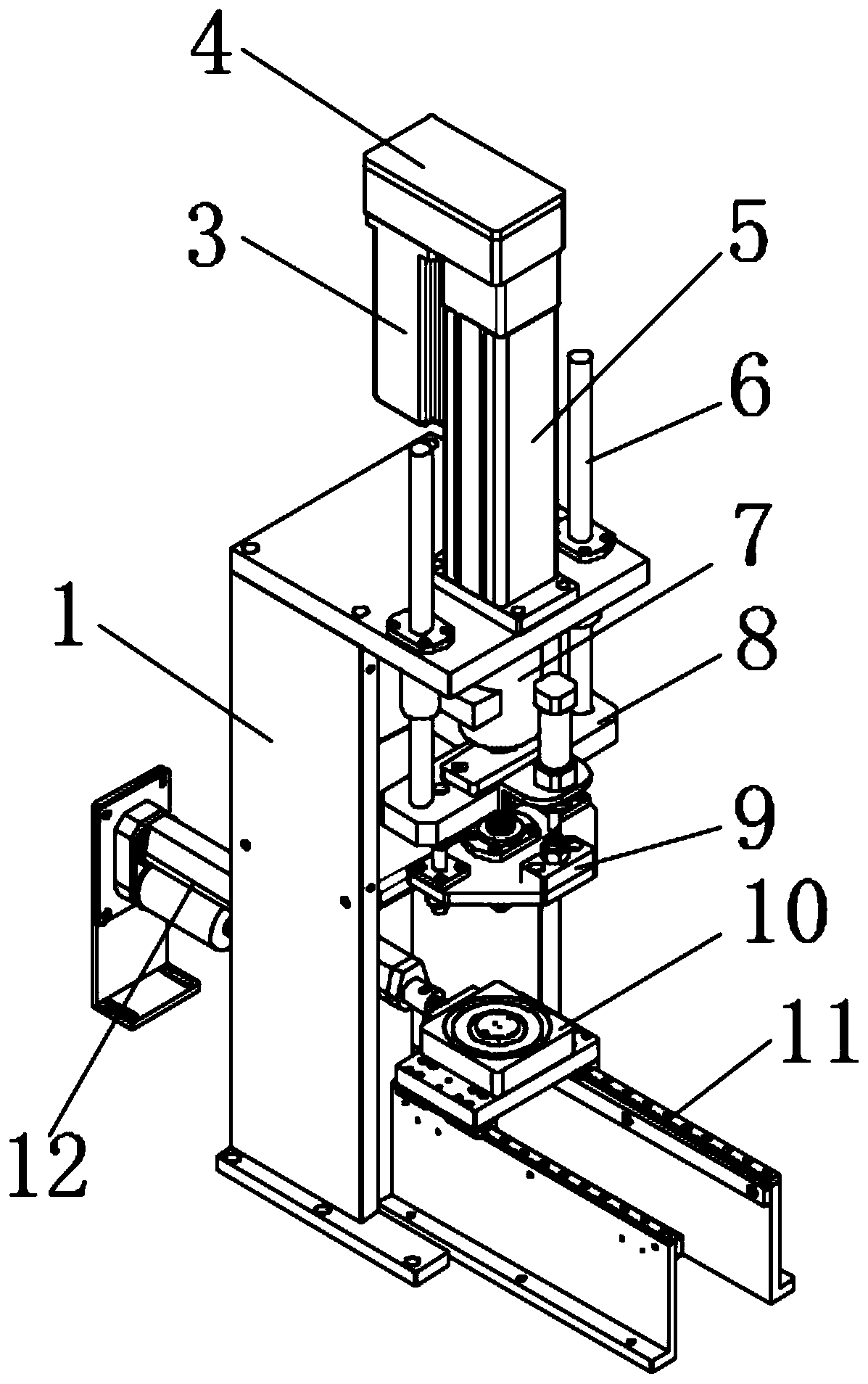
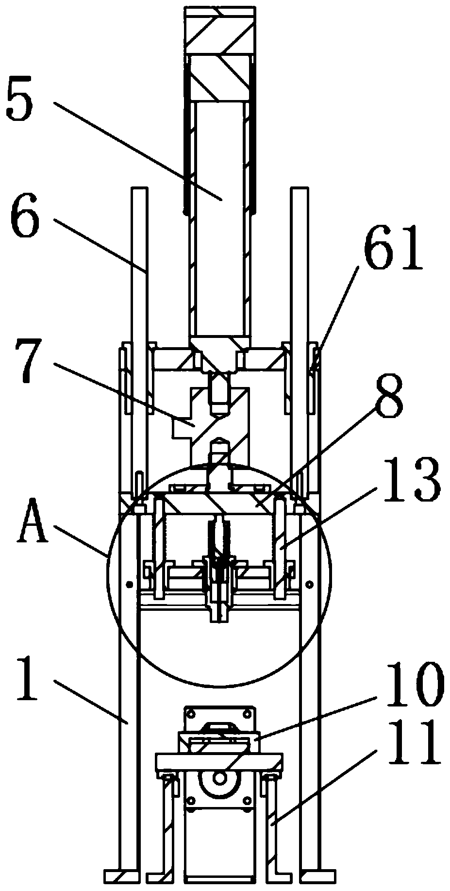
[0032] Such as figure 1 , figure 2 As shown, in this embodiment, a drug-loading plate pressing device includes an auxiliary mounting frame 1, a main lifting plate 8, an auxiliary lifting plate 9 located below the main lifting plate 8, and is arranged on the main lifting plate 8 for controlling The secondary lifting plate driving structure 22 which moves in the vertical direction relative to the main lifting plate 8 of the auxiliary lifting plate 9 is arranged on the auxiliary mounting frame 1 for controlling the main lifting plate driving structure and setting of the main lifting plate 8 moving in the vertical direction. On the auxiliary lifting plate 9, there is a pressure head 18 with a charge through hole and a punching needle 17 that is transmission-connected with the main lifting plate 8 and can slide relatively with the charge through hole on the pressure head 18. The pressure head 18 A charging plate 10 aligned with the charging through hole is arranged below, and the...

Embodiment 2

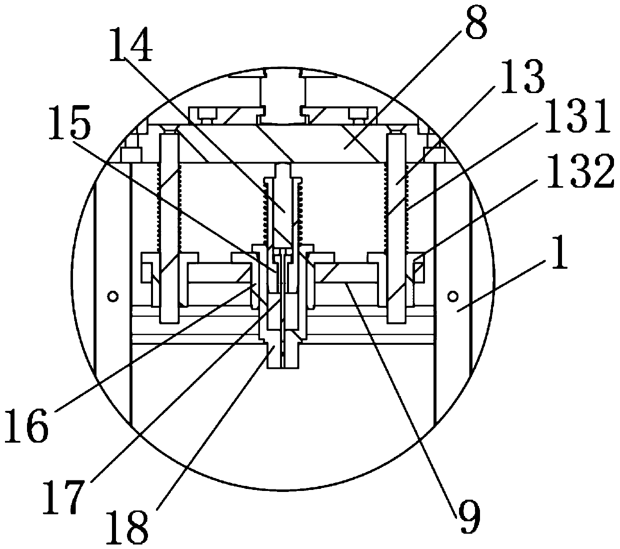
[0038] Such as image 3 , Figure 4 As shown, on the basis of the above-mentioned embodiments, in this embodiment, the end of the pressure head 18 close to the main lifting plate 8 is provided with a stroke hole that is coaxial with the through-hole of the charge and has a diameter larger than the through-hole of the charge. A push rod sleeve 15 with a stepped hole is slidably installed in the stroke hole described above, the small hole of the stepped hole points to the charge through hole, and one end of the punching needle 17 passes through the stepped hole in the push rod sleeve 15 and is connected with the loading hole. The drug through hole is matched with the installation, and the other end of the punching needle 17 is located in the large hole of the stepped hole, and the punching pin ejector rod 14 connected with the main lifting plate 8 is slidably arranged in the large hole of the stepped hole.

[0039]Utilize the cooperation of push rod cover 15 and punch push rod ...

Embodiment 3

[0042] Such as Figure 4 As shown, on the basis of the above-mentioned embodiment 3, in this embodiment, a T-shaped punching needle sleeve 19 is provided between the punching needle 17 and the small hole of the stepped hole. The punching needle cover 19 is installed in cooperation with the stepped hole, and the punching needle cover 19 is designed to be T-shaped and can prevent the punching needle cover 19 from falling off from the aperture of the stepped hole. The punching needle sleeve 19 is matched with the small hole of the stepped hole. By leaving a gap, the punching needle 17 can have a certain space for fine-tuning, so as to adapt to the assembly deviation caused by the processing error and avoid the bending of the punching needle 17 affected by the processing error. If the deformation, movement is interfered or broken, by using the punching needle sleeve 19 to cover the outside of the punching needle 17, the risk of bending deformation or breaking of the punching needl...


PUM


Abstract

The invention discloses an explosive pressing device of an explosive charging plate. The explosive pressing device comprises an auxiliary mounting frame, a main lifting plate, an auxiliary lifting plate, an auxiliary lifting plate driving structure, a main lifting plate driving structure, a pressing head arranged on the auxiliary lifting plate and a punching needle. The explosive charging plate aligned with an explosive charging through hole is arranged below the pressing head, and the explosive charging through hole communicates with an explosive charging pipe. The explosive pressing device has the beneficial effects that the punching needle can slide in the explosive charging through hole to press explosive in the explosive charging through hole into the explosive charging plate, the size of the explosive charging through hole can be designed to control the explosive charging accuracy, the explosive charging accuracy can reach the millimeter level, remote and automatic control is better achieved, the automatic degree of the explosive charging process is improved, and a worker is prevented from being in direct contact with explosive so that the safety performance can be enhanced.Automatic and continuous production can be achieved, the explosive charging efficiency is improved, the explosive charging quality is improved, and the explosive charging quality stability is improved.

Description

technical field [0001] The invention relates to the technical field of explosive charge, in particular to a charge plate pressing device. Background technique [0002] At present, most of the explosives, explosives, and civil hazardous chemicals industries use manual feeding and traditional production methods of balance measurement. The product weight is stable, the production efficiency is low, the degree of automation is low, and manual direct contact with pharmaceuticals Contact, human-machine isolation cannot be achieved, and there are major security risks. Weighing measurement control relies on manual experience, poor product consistency, resulting in high cost of mass production, unable to form efficient production capacity, which seriously restricts the development of the industry. Contents of the invention [0003] In order to overcome the deficiencies of the prior art, the present invention provides a drug-loading plate pressing device, which is used to improve t...

Claims


Application Information

Patent Timeline
Patent Type & Authority Applications(China)
IPC IPC(8): F42B33/02
Inventor 刘辉熊长江李培
Owner 绵阳市奥派科技有限公司
Why Eureka
Try Eureka