Ion source filamentworking method

A working method and ion source technology, applied in the field of mass spectrometry analysis, can solve the problems of inaccurate measurement of instruments, excessive filament current, waste, etc., and achieve the effect of accurate replacement time and prolonging service life.

Active Publication Date: 2019-05-10
FOCUSED PHOTONICS
View PDF11 Cites 2 Cited by
  • Summary
  • Abstract
  • Description
  • Claims
  • Application Information

AI Technical Summary

Problems solved by technology

[0004] (1) The filament current is too large, basically around 1A, resulting in frequent replacement of the filament, and the filament needs to be replaced after one year of use;
[0005] (2) Due to the continuous online detection, the measured gas contains a large amount of impurities, and the ion source is easily contaminated by the measured gas after a period of use, but it is impossible to accurately determine the replacement time of the filament. If the replacement is too late, the measurement of the instrument will not be accurate. Early leads to waste and frequent replacement

Method used


Image

  • Ion source filamentworking method
  • Ion source filamentworking method

Examples


Embodiment 1

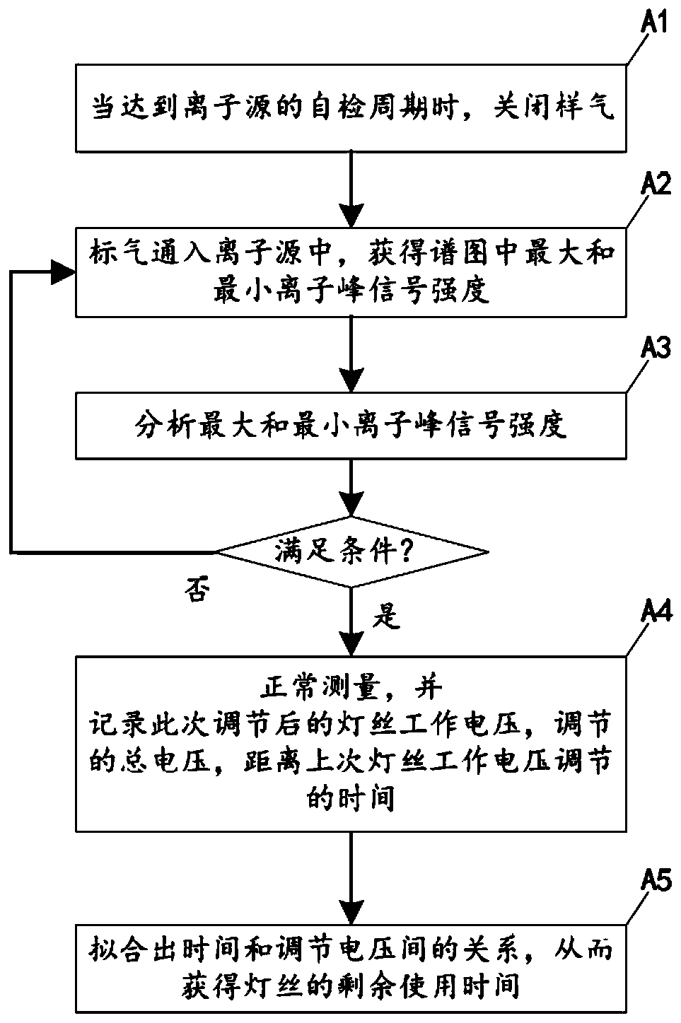
[0028] figure 2 A flow chart of the working method of the ion source filament in the embodiment of the present invention is schematically given, as figure 2 As shown, the working method of the ion source filament comprises the following steps:

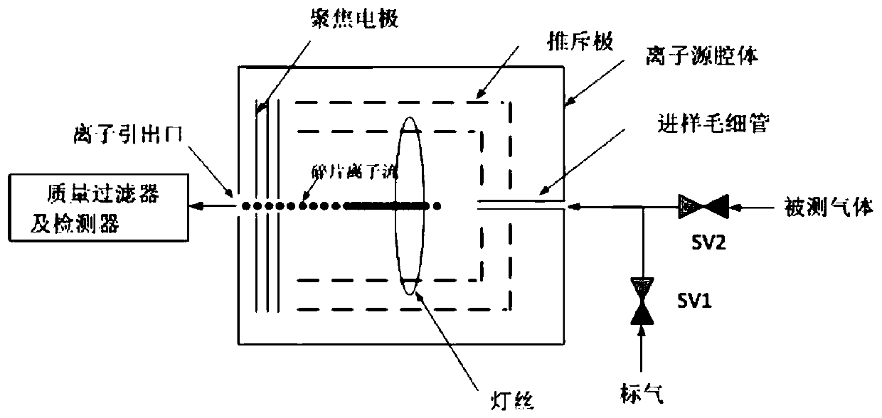
[0029] (A1) When the self-test cycle of the ion source is reached, the sample gas is turned off; the ion source is an EI source;

[0030] (A2) The standard gas is passed into the ion source to obtain the maximum ion peak signal intensity I in the spectrogram max , the minimum ion peak signal intensity I min ;

[0031] (A3) Analytical ion peak signal intensity I max , I min :

[0032] If I max ≤I s , and the signal strength I min When the signal-to-noise ratio is greater than N, end the self-inspection and enter step (A4); s is the upper limit of ion peak intensity;

[0033] If I max ≤ I s , and the signal strength I min When the signal-to-noise ratio is less than N, increase the working voltage U of the filament, U≤U m...

Embodiment 2

[0040] An application example of the working method of the ion source filament according to Embodiment 1 of the present invention.

[0041] In this application example, the ion source adopts EI source, and the initial working voltage of the filament is U 0 , in step (A3), the working voltage of the filament is increased by Δu each time, that is, the step size of the increase is Δu. It can be seen that in each self-test, if the working voltage of the filament is to be adjusted, each self-test The working voltage of the filament adjusted in ΔU=K·Δu, K is a positive integer.


PUM


Abstract

The invention provides an ion source filament working method. The ion source filament working method comprises the following steps that (A1), sample gas is closed when a self-test cycle of an ion source is reached; (A2), standard gas is introduced into the ion source, and the maximum ion peak signal intensity I<max> and the minimum ion peak signal intensity I<min> in a spectrum are obtained; (A3),the ion peak signal intensity I<max> and I<min> are analyzed; (A4), the standard gas is closed and the sample gas is opened, normal measuring is conducted, the filament working voltage U<n> after current adjustment, the total regulated voltage delta U<n> and the time from the last working voltage adjustment of the filament delta t<n> are recorded; and (A5), according to the recorded delta U<1>, delta U<2>...delta U<n> and the corresponding delta t<1>, delta t<2>...delta t<n>, fitting of delta U=f(t) is conducted, and the remaining service time delta t of the filament is obtained, wherein U<max>-U<n>=f(delta t). The method has the advantage that prediction of the remaining service life is accurate.

Description

technical field [0001] The invention relates to mass spectrometry, in particular to the working method of the ion source filament. Background technique [0002] The ion source of the mass spectrometer used in the online mass spectrometer is mainly the electron bombardment ion source, that is, the EI source. [0003] figure 1 A schematic diagram of the structure of the external ion source is given schematically, such as figure 1 As shown, in a vacuum environment, the gas to be measured is introduced into the ion vacuum chamber, and the filament emits an electron flow to bombard the gas to be measured, and then ionize the gas to be measured. The ionized fragment ions pass through the extraction electrode, focusing electrode, acceleration After the electrodes enter the mass filter for separation and analysis. The disadvantages of this way of working are: [0004] (1) The filament current is too large, basically around 1A, resulting in frequent replacement of the filament, a...

Claims


Application Information

Patent Timeline
IPC IPC(8): G01R31/44G01N27/62H01J49/14
Inventor 张进伟俞大海
Owner FOCUSED PHOTONICS
Why Eureka
Try Eureka