Waste gas treatment device for chemical raw material production

A technology for waste gas treatment devices and chemical raw materials, applied in chemical instruments and methods, dispersed particle separation, separation methods, etc., can solve problems such as troublesome treatment, increased cost of activated carbon replacement, and excessive particulate matter, and achieves improved contact and accurate replacement time. Effect

Pending Publication Date: 2021-12-14
陈燕珍
View PDF0 Cites 0 Cited by
  • Summary
  • Abstract
  • Description
  • Claims
  • Application Information

AI Technical Summary

Problems solved by technology

[0003] According to the form of pollutants, chemical waste gas can be divided into particulate pollutants and gaseous pollutants. Due to the high content of toxic gases in chemical waste gas and the unclear composition, there is no clear method for subsequent treatment of waste gas. Therefore, at present, when treating exhaust gas particles, most of the particulate pollutants in the exhaust gas will be adsorbed by activated carbon. In the existing exhaust gas treatment devices, the validity period of activated carbon is 3 to 6 months, usually three months. Replace the activated carbon once, but when there are many solid particles in the exhaust gas, the activated carbon will be saturated usually three months ago. If it is not replaced in time, the particulate matter in the exhaust gas will exceed the standard, resulting in troublesome follow-up treatment, or when there are few solid particles in the exhaust gas , after three months, the activated carbon can still continue to adsorb but is replaced, resulting in an increase in the cost of activated carbon replacement. Therefore, we propose a waste gas treatment device for the production of chemical raw materials

Method used


Image

  • Waste gas treatment device for chemical raw material production
  • Waste gas treatment device for chemical raw material production
  • Waste gas treatment device for chemical raw material production

Examples


Embodiment 1

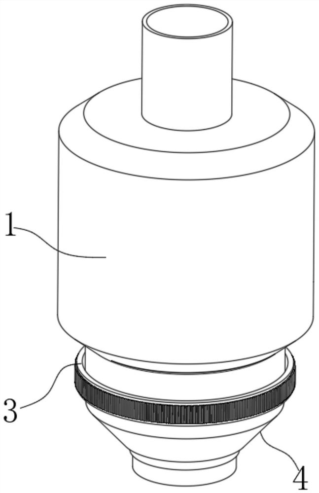
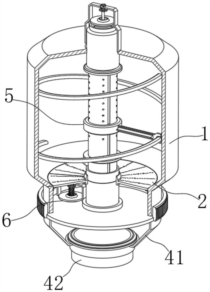
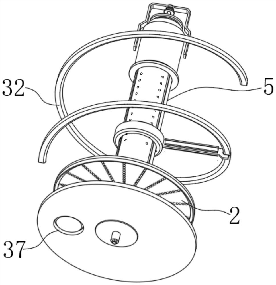
[0027] see figure 1 and figure 2 , a chemical raw material production waste gas treatment device in the illustration, including a treatment cylinder 1 for holding activated carbon, a filter plate 2 is fixed on the inner wall of the bottom of the treatment cylinder 1, and also includes a cover 3 and a stirring assembly 5, the cover 3 Covered on the bottom of the processing cylinder 1, and the bottom end of the cover 3 is connected with a connecting piece 4 that is docked with the exhaust gas pipeline. The stirring assembly 5 used to stir the activated carbon in the processing cylinder 1 to improve the adsorption effect is installed in the processing cylinder 1, and It is connected with the cover 3, and the detection mechanism 6 for detecting the saturation of activated carbon is installed on the top of the cover 3 and the stirring assembly 5.

[0028] It should be noted that: in this solution, an external gear ring is fixed on the outside of the cover 3, so that the belt pull...

Embodiment 2

[0040] see Figure 6 and Figure 7 , this embodiment is further described for Example 1. The limiting member 10 in the figure includes two connecting frames 24, and the two connecting frames 24 are respectively fixed on both sides of the bottom end of the rotating sleeve 8, and the two connecting frames 24 slide There are snap-in rods 25 plugged in, and two spacer slots 26 are arranged on the inner side of the connecting sleeve 7, and the outer ends of the snap-in rods 25 are fixed with snap-in balls 27 that are compatible with the spacer slots 26, and the outer ends of the snap-in rods 25 are covered with There is an extruding spring 28 against the stuck ball 27 and the connecting frame 24.

[0041] In this embodiment, the position of the rotating sleeve 8 can be controlled by designing the locking ball 27 in the limiting member 10 to move in different limiting grooves 26, so that the rotating sleeve 8 can rotate stably after each adjustment. The driving of the linkage mech...

Embodiment 3

[0044] see figure 1 and figure 2 , this embodiment is further described for other examples. A chemical raw material production waste gas treatment device in the illustration includes a treatment cylinder 1 for holding activated carbon. A filter plate 2 is fixed on the inner wall of the bottom of the treatment cylinder 1. The cover 3 and the stirring assembly 5, the cover 3 is set on the bottom of the treatment cylinder 1, and the bottom end of the cover 3 is connected with the connecting piece 4 connected with the waste gas pipeline, which is used to stir the activated carbon in the treatment cylinder 1 to improve the adsorption effect The component 5 is installed in the processing cylinder 1 and connected with the cover 3, and the detection mechanism 6 for detecting the saturation of activated carbon is installed on the top of the cover 3 and the stirring component 5 .

[0045] Also, see figure 2 , the connecting piece 4 in the figure includes a tapered sleeve 41 fixed at...


PUM


Abstract

The invention discloses a waste gas treatment device for chemical raw material production. The waste gas treatment device comprises a treatment cylinder for containing activated carbon, a sleeve cover and a stirring assembly, a filter screen plate is fixed to the inner wall of the bottom of the treatment cylinder, the sleeve cover sleeves the bottom of the treatment cylinder, the bottom end of the sleeve cover is connected with a connecting piece in butt joint with a waste gas pipeline, the stirring assembly used for stirring activated carbon in the treatment cylinder to improve the adsorption effect is installed in the treatment cylinder and connected with the sleeve cover, and a detection mechanism used for detecting the saturation degree of activated carbon is installed at the top end of the sleeve cover and the top end of the stirring assembly. According to the waste gas treatment device disclosed by the invention, the stirring assembly and the detection mechanism are additionally arranged on the treatment cylinder, so while waste gas is treated, activated carbon can be stirred, contact of the activated carbon with waste gas is improved, and the adsorption effect of the activated carbon is better; and meanwhile, two detection mechanisms are matched to detect waste gas inlet pressure and waste gas exhaust pressure, the saturation condition of the activated carbon in the treatment cylinder can be known through comparison, and follow-up replacement time of the activated carbon is more accurately controlled.

Description

technical field [0001] The invention relates to the technical field of waste gas treatment, in particular to a waste gas treatment device for chemical raw material production. Background technique [0002] Chemical waste gas refers to the toxic and harmful gas discharged from chemical plants in chemical production. Chemical waste gas often contains many types of pollutants, complex physical and chemical properties, and different toxicity. It seriously pollutes the environment and affects human health. Different chemical production The chemical waste gas composition produced by the industry varies greatly. [0003] According to the form of pollutants, chemical waste gas can be divided into particulate pollutants and gaseous pollutants. Due to the high content of toxic gases in chemical waste gas and the unclear composition, there is no clear method for subsequent treatment of waste gas. Therefore, at present, when treating exhaust gas particles, most of the particulate pollu...

Claims


Application Information

Patent Timeline
IPC IPC(8): B01D53/10
CPCB01D53/10
Inventor 陈燕珍
Owner 陈燕珍
Why Eureka
Try Eureka