
Induction cooker coil panel capable of achieving circuit optimization and efficiently heating tray simultaneously

A technology of coil disk and induction cooker, which is applied to electric heating fuel, lighting and heating equipment, coil device, etc., can solve the problems of increasing copper loss, increasing the volume and weight of the coil disk of the induction cooker, and the failure of single-tube quasi-resonant converters to work. , to meet the impedance requirements and expand the scope of application

Pending Publication Date: 2019-05-10
NANJING UNIV OF AERONAUTICS & ASTRONAUTICS
View PDF0 Cites 0 Cited by
  • Summary
  • Abstract
  • Description
  • Claims
  • Application Information

AI Technical Summary

Problems solved by technology

However, the additional transformer will increase the volume and weight of the coil disk of the induction cooker, and further increase the copper loss; at the same time, if a transformer and a resonant network are added to the single-tube quasi-resonant converter, the impedance model of the coil disk will be equivalent to a very large magnetizing inductance Connected in parallel with the resistor, which leads to the inability of the single-tube quasi-resonant converter to work in the quasi-resonant state

Method used


Image

  • Induction cooker coil panel capable of achieving circuit optimization and efficiently heating tray simultaneously
  • Induction cooker coil panel capable of achieving circuit optimization and efficiently heating tray simultaneously
  • Induction cooker coil panel capable of achieving circuit optimization and efficiently heating tray simultaneously

Examples


Embodiment 1

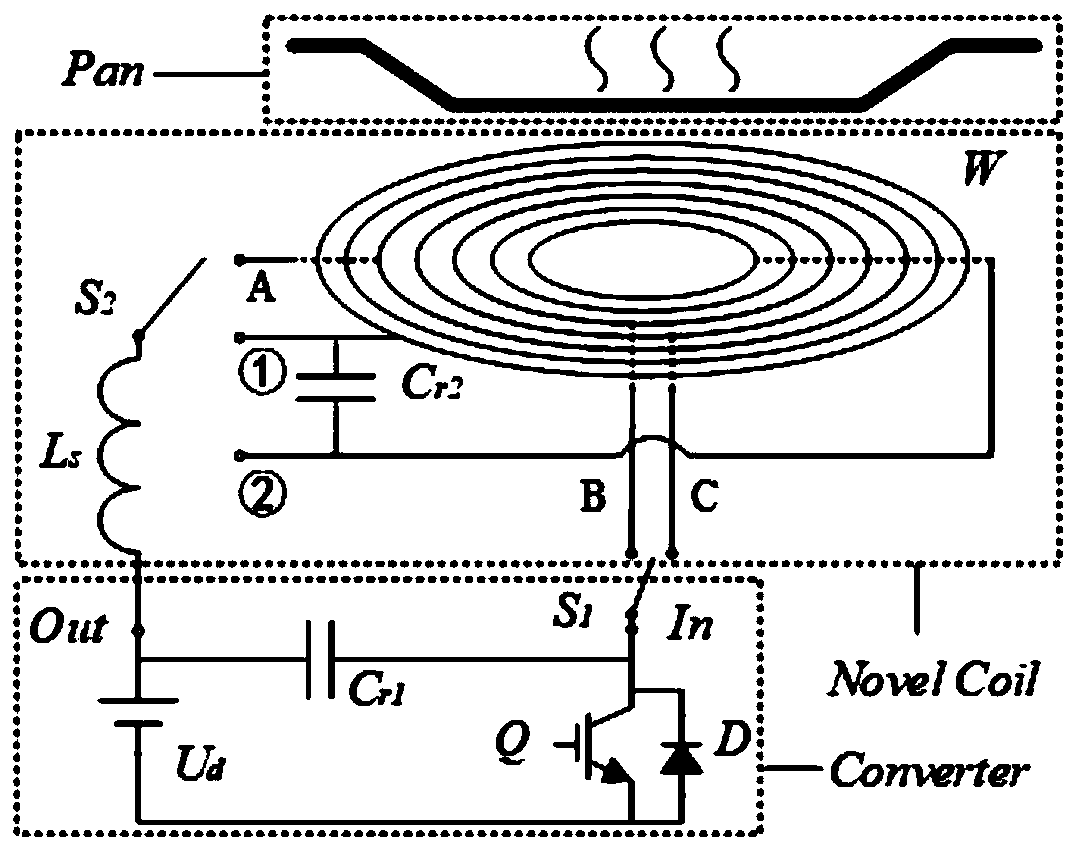
[0056] Figure 5 (a) is a schematic structural view of the first embodiment of the coil plate of an induction cooker that takes into account both circuit optimization and efficient heating of the hob according to the present invention, such as Figure 5 As shown in (a), in the first embodiment, the coil coil winding W is wound in a single-layer and whole section to reduce the volume and weight of the coil coil, and the tap A is drawn from the winding, and the coil coil winding W passes through ports ①, ② with additional capacitance C r2 The parallel connection forms a resonant unit. The winding between port ① and tap A is W 1 , the winding between port ② and tap A is W 2 . Additional inductance L s One end through the switch S 1 It is connected with port ① or port ②, that is, it is connected in series with the resonant unit to form an impedance transformation network, and then connected with the output end of the converter. where the additional inductance L s It can be...

Embodiment 2

[0070] Figure 5 (b) is a schematic structural view of the second embodiment of the coil plate of an induction cooker that takes into account circuit optimization and efficient heating of the plate of the present invention, such as Figure 5 As shown in (b), in the second embodiment, the coil coil W is wound in a double-layer and whole section, so as to increase the mutual inductance between each part of the winding and improve the heating efficiency of the coil coil W. Tap A, tap B, and tap C, taps A, B, and C can be set at any position in the double-layer winding, and the coil winding passes through ports ①, ② and the additional capacitor C r2 Parallel connections form a resonant unit. Where the winding between tap A and tap B is W 1 , the whole section of winding removes W 1 The rest is W 2 , the winding between tap A and tap C is W 3 , the whole section of winding removes W 3 The rest is W 4 . Additional inductance L s The tap A is connected in series with the res...

Embodiment 3

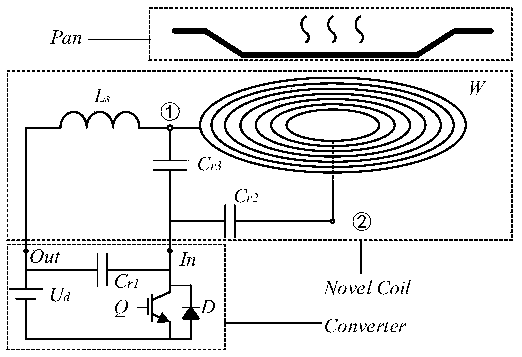
[0078] image 3It is a structural schematic diagram of the third embodiment of an induction cooker coil pan that takes into account circuit optimization and efficient heating of the hob, as shown in the present invention. image 3 As shown, in the third embodiment, the coil coil W is wound in a single-layer and whole section to reduce the volume and weight of the coil coil, and the coil coil W passes through the port ② and the additional capacitor C r2 connected in series to form a series branch, and then with the additional capacitance C r3 Connected in parallel to form a resonance unit. Additional inductance L s Port ① is connected in series with the resonant unit to form an impedance transformation network, and then connected to the output end of the converter. where the additional inductance L s It can be wound on the coil disk magnetic core together with the coil disk winding, and the magnetic core can be added to reduce the coupling with the pot to improve the utiliz...


PUM


Abstract

The invention discloses an induction cooler coil panel capable of achieving circuit optimization and efficiently heating a tray simultaneously. The induction cooler coil panel comprises a coil panel and a converter; the coil panel comprises a coil panel magnetic core and a coil panel winding, and also comprises an equivalent impedance transformer network that is connected with the coil panel winding and the converter; the induction cooker coil panel winding at least comprises a tap, and each part of the coil panel winding heats a cooker. By using the induction cooker coil panel capable of achieving circuit optimization and efficiently heating tray simultaneously provided by the invention, through selecting the different port or tap, the self-inductance and mutual inductance of each part ofwinding of the coil panel in a resonance unit can be changed, so that the different equivalent impedance conversions are achieved, the output characteristics of the converter are optimized, and the application range of the material of the induction cooker is enlarged; meanwhile, in combination with the method for improving the work efficiency and the number of turns of the coil panel winding, theratio of the equivalent impedance of the cooker to the equivalent impedance of the coil panel is increased, and the heating efficiency of the tray can be improved under the premise of not changing the circuit structure and the device stress.

Description

technical field [0001] The invention relates to an induction cooker heating technology, in particular to an induction cooker coil disk containing at least one tap and a group of additional capacitors, and an equivalent impedance transformation method for the induction cooker coil disk. Background technique [0002] The induction cooker uses induction eddy current to heat the metal pan, that is, a high-frequency alternating current is passed into the coil plate to generate an alternating magnetic field, and electromagnetic induction is used to generate an eddy current at the bottom of the pan, and the pan is directly heated through the Joule heating effect of the eddy current. Compared with the traditional heating method, the induction cooker does not need an open flame or conduction heat, and its heating efficiency is 40% higher than that of the traditional stove. The environment is safe and hygienic, and there is no need to lay special gas pipelines. application market. ...

Claims


Application Information

Patent Timeline
Patent Type & Authority Applications(China)
IPC IPC(8): H05B6/36F24C7/06
Inventor 陈乾宏李志斌张帅张之梁任小永
Owner NANJING UNIV OF AERONAUTICS & ASTRONAUTICS
Learn More