BMO position positioning method of oct image

A positioning method and image technology, which is applied in the fields of eye testing equipment, medical science, diagnosis, etc., can solve the problems of time-consuming, missing, positioning influence, etc., and achieve the effect of solving the problem of insufficient accuracy

Active Publication Date: 2021-06-15
CENT SOUTH UNIV
View PDF24 Cites 0 Cited by
  • Summary
  • Abstract
  • Description
  • Claims
  • Application Information

AI Technical Summary

Problems solved by technology

In 2015, Miri et al. improved the above method by using the graph theory algorithm of random forest to construct the cost function. This algorithm transformed the segmentation problem into an optimization problem, and obtained the three-dimensional path of BMO with the shortest path algorithm, which improved the positioning accuracy; but the The disadvantage of the method is that it is not robust to vascular shadows, and it relies too much on the registration effect of the two-dimensional projection map and the fundus map. Once there is a mismatch, the segmentation effect will become poor
But it also greatly increases the time consumption
[0008] In 2015, Hussain et al. from the University of Melbourne in Australia proposed a BMO segmentation method based on graph search and OCT layered information. This method uses graph search to obtain the inner segment-outer segment (IS-OS) and retinal pigment The intersection point of the epithelial layer (retinal pigment epithelium, RPE) was used as the initial positioning, and then the deepest position of the inner limiting membrane layer (inner limiting membrane, ILM) was used for calibration, and a high accuracy rate was achieved; however, the surrounding tissue of the BMO point was not resolved interference with positioning
Wang et al. from the University of Iowa proposed a graph theory algorithm based on shape soft constraints, using the shape of the ILM and the texture features of the BM layer (Bruch's Membrane), and using the information of two-dimensional high-definition OCT and 3D SD-OCT to construct weights The figure estimates the BMO curve on SD-OCT, which is close to the effect of the semi-automatic algorithm; the disadvantage is that the algorithm relies on the HD-OCT centered on the optic disc, and relies on the effect of two OCT image registration
[0010] In 2014, Belghith et al. proposed a model based on deconvolution, which used a curve to model the Bruch film layer, a convolution kernel to model the thickness, and then used the Markov Monte Carlo method to model the The parameters of the model are solved, and the too short line segments are removed through constraints, and finally the problem is transformed into missing data filling, which effectively improves the accuracy of the segmentation, but the lack of longer samples, that is, the larger blood vessel shadows, will cause problems for the positioning of the method. greater impact
In 2015, Fu Huazhu and others proposed a method using a low-rank matrix to segment the BMO position, and obtained the BMO segmentation point by comparing the error curve and the sigmoid curve; the accuracy of this method needs a lot of experiments to prove, and it will Worse by the paraoptic atrophic arc, not robust to glaucoma samples
Wu et al. from Nanjing University of Technology proposed a block matching BMO segmentation method based on support vector machines, which achieved a dice coefficient of 0.919; The accuracy of segmentation in large OCT images needs to be improved

Method used


Image

  • BMO position positioning method of oct image
  • BMO position positioning method of oct image
  • BMO position positioning method of oct image

Examples


Embodiment Construction

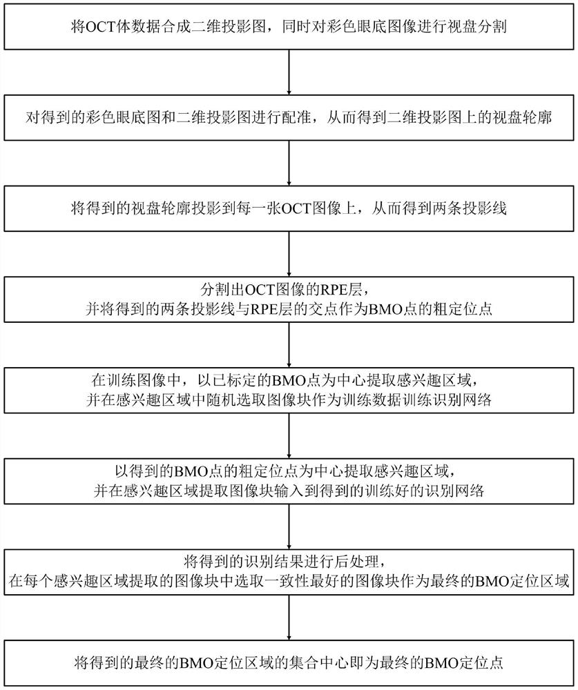
[0042] Such as figure 1 Shown is the method flowchart of the method of the present invention: the BMO position positioning method of this OCT image provided by the present invention comprises the following steps:

[0043] S1. Synthesize the OCT volume data into a two-dimensional projection image, and perform optic disc segmentation on the color fundus image at the same time;

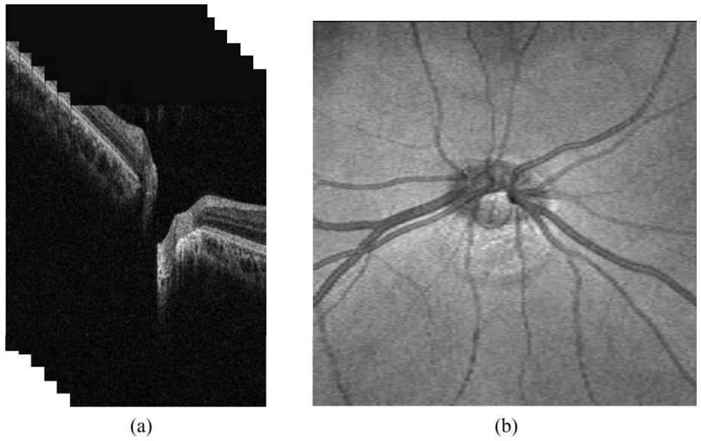
[0044] In the specific implementation, the SD-OCT images are added and normalized by column to obtain the two-dimensional projection map of the OCT image, as figure 2 shown; among them, figure 2 (a) is a single SD-OCT image; figure 2 (b) 2D projection image synthesized from 128 SD-OCT images;

[0045] At the same time, the optic disc in the color fundus image can be segmented by using the method of Hough circle detection;

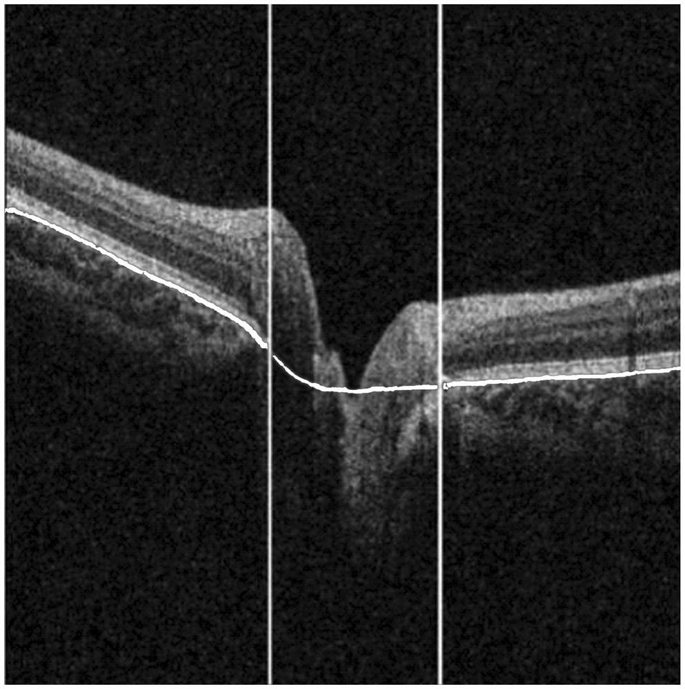
[0046] S2. Register the color fundus map and the two-dimensional projection map obtained in step S1, so as to obtain the optic disc outline on the two-dimensional projection ma...


PUM


Abstract

The invention discloses a BMO position positioning method of an OCT image, comprising synthesizing a two-dimensional projection image and performing optic disc segmentation on a color fundus image; registering the color fundus image and the two-dimensional projection image to obtain the optic disc outline on the two-dimensional projection image; The optic disc outline is projected onto the OCT image to obtain two projection lines; the RPE layer is segmented and the rough positioning point of the BMO point is obtained; the recognition network is trained; the region of interest is extracted centered on the rough positioning point of the BMO point and input into the recognition network; the recognition result is Perform post-processing and select the image block with the best consistency as the final BMO positioning area; the center of the final BMO positioning area is the final BMO positioning point. The method of the present invention is superior to the existing methods in the accuracy of BMO positioning, and is closer to the result of manual calibration by experts, and the present invention can reduce the influence of the surrounding tissues of the BMO on automatic positioning, and help clinicians automatically calibrate the BMO position.

Description

technical field [0001] The invention specifically relates to a BMO position positioning method of an OCT image. Background technique [0002] Glaucoma is the second leading cause of blindness in the world. It destroys the axons of optic ganglion cells around the optic nerve head, resulting in loss of vision. Due to the irreversibility of glaucoma, early detection, early detection and early treatment of glaucoma can slow down the progress of the disease. However, because the pathogenesis of glaucoma has not been fully clarified, the research on the risk factors of glaucoma is still a hot issue at present. [0003] Optical coherence tomography (OCT) technology has only been used clinically in ophthalmology for 20 years, and its technological innovation has been rapid, and it has now become one of the most important clinical examinations in ophthalmology. This technology emits coherent light to the tissue, recycles the reflected light and scattered light of the tissue, and co...

Claims


Application Information

Patent Timeline
Patent Type & Authority Patents(China)
IPC IPC(8): A61B3/10A61B5/00A61B3/14
Inventor 陈再良彭鹏沈海澜魏浩曾梓洋梁毅雄
Owner CENT SOUTH UNIV
Why Eureka
Try Eureka