
Patch antenna far-field pattern analysis method based on equivalent surface magnetic current spacing

A patch antenna and analysis method technology, applied in resonant antenna, basically flat resonant element, design optimization/simulation, etc., can solve problems such as low precision, difficult coupling modeling, and large amount of calculation

Pending Publication Date: 2022-06-03
XIDIAN UNIV
View PDF0 Cites 0 Cited by
  • Summary
  • Abstract
  • Description
  • Claims
  • Application Information

AI Technical Summary

Problems solved by technology

But the disadvantage is that compared with other methods, the accuracy is lower, and it is difficult to carry out coupling modeling.
The cavity model theory proposed by Luo Yuanzhi in 1979 is a two-dimensional approximate analysis method, and it is applicable to all regular shapes, but its disadvantage is that it cannot analyze patches with larger thickness
The most accurate ones are various full-wave analysis methods such as finite element method, time-domain finite difference method and method of moments, but its disadvantage is that the calculation amount is huge and the process is relatively complicated

Method used


Image

  • Patch antenna far-field pattern analysis method based on equivalent surface magnetic current spacing
  • Patch antenna far-field pattern analysis method based on equivalent surface magnetic current spacing
  • Patch antenna far-field pattern analysis method based on equivalent surface magnetic current spacing

Examples


Embodiment 1

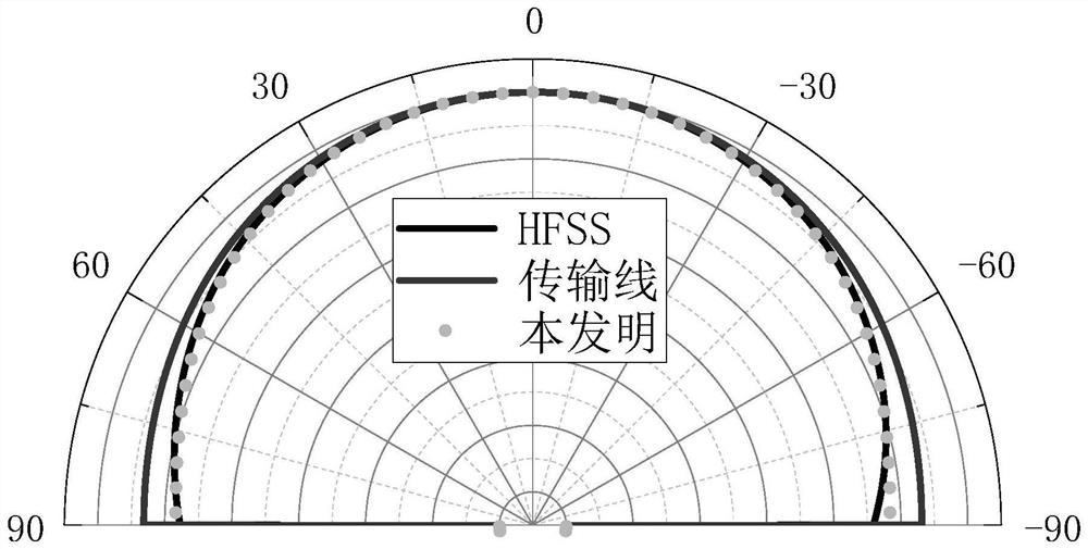
[0075] Simulation Example 1: The radiation performance of a patch antenna with a center operating frequency f=3GHz, a relative dielectric constant of 2.2, and a dielectric substrate thickness of 2.87mm is taken as an analysis case.

Embodiment 2

[0076] Simulation Example 2: The radiation performance of a patch antenna with a center operating frequency f=10 GHz, a relative dielectric constant of 2.2, and a dielectric substrate thickness of 1.588 mm is taken as an analysis case.

Embodiment 3

[0077] Simulation Example 3: The radiation performance of a patch antenna with a center operating frequency f=2.45GHz, a relative dielectric constant of 4.4, and a dielectric substrate thickness of 1.6mm is taken as an analysis case.

[0078] 2. Simulation content and results

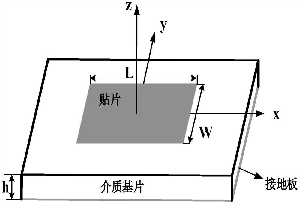
[0079] figure 2 It is a schematic diagram of the structure of the patch antenna; image 3 and Figure 4 The comparison of the E-plane and H-plane patterns calculated by the method in Example 1, the calculation of the transmission line analysis method and the simulation results of the numerical software HFSS are given respectively; Comparison of the beamwidths of the two principal surfaces calculated by the HFSS software.

[0080] Table 1 embodiment 1 electrical performance parameter comparison

[0081] Electrical performance parameters this invention Transmission Line Analysis Methods HFSS Maximum Directivity Coefficient / dBi 7.99 6.91 8.16 Main beam pointing θ / °

0...


PUM

PropertyMeasurementUnit
thicknessaaaaaaaaaa
thicknessaaaaaaaaaa
thicknessaaaaaaaaaa

Abstract

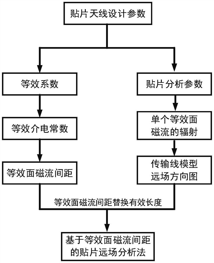
The invention discloses a patch antenna far-field pattern analysis method based on equivalent surface magnetic current spacing, which comprises the following steps: determining design parameters and material parameters of a patch antenna, and calculating analysis parameters of the patch antenna; the analysis parameters are combined with the theoretical assumption of a patch antenna transmission line analysis method, the radiation of a single equivalent surface magnetic current is determined, the directional diagram function of the transmission line analysis method is determined, the equivalent coefficient of the material is obtained, the equivalent relative dielectric constant of the microstrip line is further obtained, and the equivalent surface magnetic current interval is finally obtained; and according to the equivalent surface magnetic current spacing and the theoretical assumption of the transmission line analysis method, obtaining a patch antenna far-field pattern based on the equivalent surface magnetic current spacing, and analyzing the radiation characteristics of the patch antenna. According to the method, the radiation characteristics of the patch antenna can be accurately analyzed, and the method has very strong engineering significance on the electrical performance analysis of the patch antenna in actual work.

Description

technical field [0001] The invention belongs to the technical field of antennas, and in particular relates to a method for analyzing the far-field pattern of a patch antenna based on an equivalent surface magnetic current spacing, which can be used to guide the electrical performance analysis of the patch antenna in practical work. Background technique [0002] With the increase in the amount of data transmitted in modern communication, there are higher requirements for the overall performance of the antenna, such as multi-band, high gain, etc. Among various types of antennas, patch antennas, as an important part, have developed rapidly in the past 50 years. Patch antennas are loved by researchers because of their advantages of small weight, small volume, low cost, and ease of manufacture, and have great potential. [0003] There are many methods for analyzing the far-field pattern of patch antennas. Among them, the most widely used is the transmission line analysis method ...

Claims


Application Information

Patent Timeline
Patent Type & Authority Applications(China)
IPC IPC(8): G06F30/20H01Q9/04
CPCG06F30/20H01Q9/0407Y02E60/00
Inventor 王伟赵子晨曹晨娄顺喜保宏蒋柏峰钟剑锋胡瑞贤徐文华连少凡
Owner XIDIAN UNIV
Learn More