s/ku dual frequency co-aperture linearly polarized phased array scanning antenna

A scanning antenna, common aperture technology, applied to antenna unit combinations, antennas, resonant antennas and other directions with different polarization directions, can solve the problem of inconvenient fixing and installation of multi-element antenna arrays, power capacity can not meet high power transmission, can not meet the structure Compactness and other issues, to achieve the effect of improving cross-polarization isolation, light weight and compact structure

Active Publication Date: 2021-01-01
10TH RES INST OF CETC
View PDF11 Cites 0 Cited by
  • Summary
  • Abstract
  • Description
  • Claims
  • Application Information

AI Technical Summary

Problems solved by technology

First of all, for the Ku frequency band, its frequency range is 12-18GHz, so the working wavelength is short, and the size of the scanning angle has great restrictions on the layout of the common-aperture antenna; while the S frequency range is 1.55-3.4GHz, so the unit The size is large, and the number of units is less distributed in the limited size space. To meet the high power index requirements of the radar, higher requirements are put forward for the power capacity of the S-band unit antenna.
[0005] China Patent Publication No. (SN106252858.A) discloses the S / X band co-aperture miniaturized planar antenna, in which the S and X band units are all in the form of microstrip patches, and the power capacity cannot meet the needs of high power transmission
A feeding structure and a dual-frequency common-aperture antenna disclosed in Chinese Patent Publication No. (SN106558764.A) also adopt the form of a microstrip radiation patch, and the feeding method is side-feeding, which cannot meet the requirements of a compact structure.
Chinese patent (SN107689490.A) discloses that the Ka and Ku radar working frequency band co-aperture dual-frequency array antennas with double substrate integrated waveguide loading adopt dipole form, which is inconvenient for multi-element antenna array fixing and installation. Chinese Patent Publication No. (SN105846114.A) The disclosed dual-band common-aperture antenna adopts the common-aperture design of waveguide slots and long-slot antennas, but this invention is only aimed at arrays with small frequency intervals such as C and L bands and similar unit sizes
To sum up, none of the designs in the above patents can be applied to design requirements such as S / Ku common aperture with large frequency intervals and low-frequency antennas that require high power capacity.

Method used


Image

  • s/ku dual frequency co-aperture linearly polarized phased array scanning antenna
  • s/ku dual frequency co-aperture linearly polarized phased array scanning antenna
  • s/ku dual frequency co-aperture linearly polarized phased array scanning antenna

Examples


Embodiment Construction

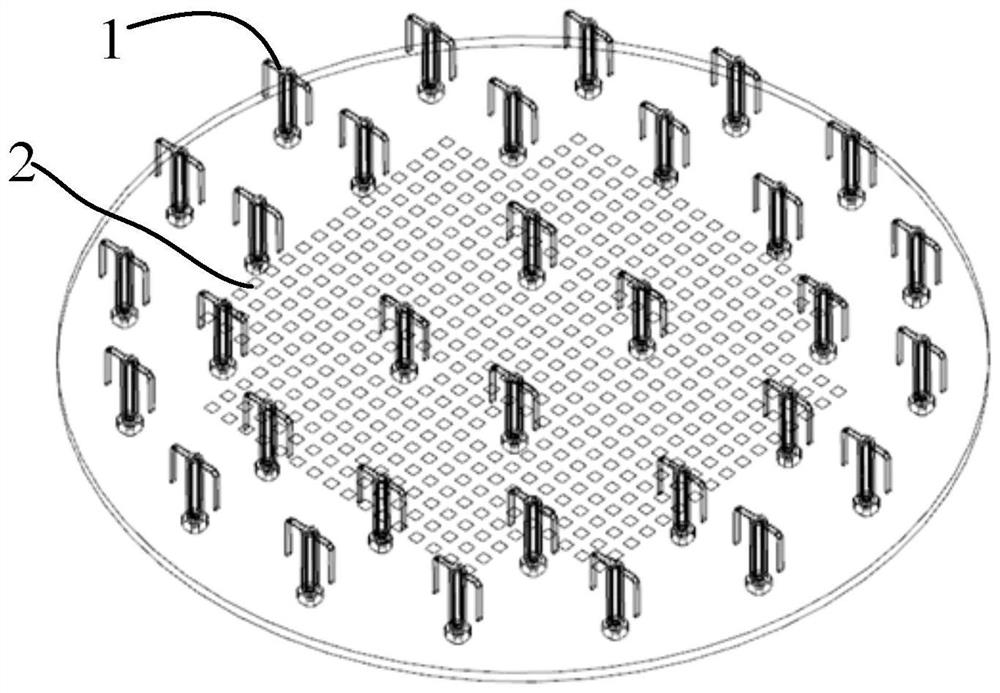
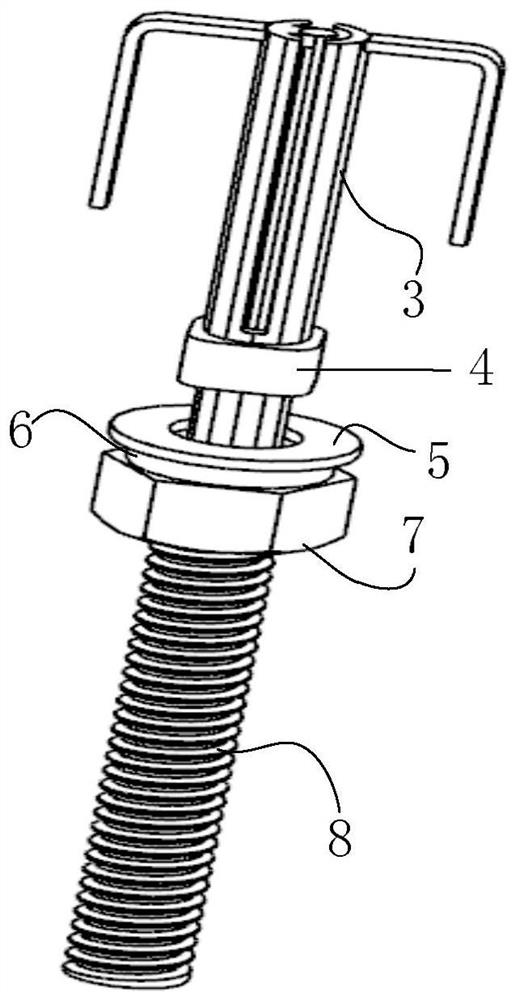
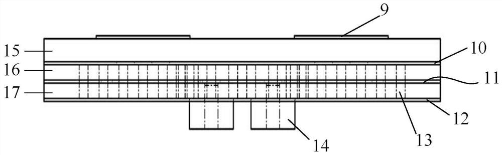
[0016] refer to figure 1 , in the embodiment described below, the S / Ku dual-frequency co-aperture linearly polarized phased array scanning antenna includes: S-band dipole antennas (1) distributed on the antenna mounting board in a circular array array and The area array is distributed in rows and columns and covers the Ku-band microstrip patch 2 on the dielectric board. Ku frequency band microstrip patch 2 arrays are distributed on the cross rectangular plane of the dielectric plate to form Ku frequency band microstrip array, and Ku frequency band microstrip patch 2 arrays are distributed on the dielectric plate cross cross rectangular plane to form Ku frequency band microstrip array The Ku array is 24×24, and the 4×4 Ku array with a 90-degree cut angle at the four corners is attached to the circular antenna mounting plate; the square array composed of four S-band dipole oscillators is embedded in the Ku In the band microstrip array, the remaining arrays of S-band dipole osci...


PUM


Abstract

The invention provides an S / Ku dual-frequency common-caliber linear polarization phased array scanning antenna, which aims to provide a composite antenna which is easy to realize dual polarization andsimply processed. The invention is realized by the following technical scheme: a Ku-band micro-strip patch array is distributed on the crisscross rectangular plane of a dielectric plate to form a Ku-band micro-strip array surface, wherein the Ku array surface is a cut-angle array, and the Ku array surfaces at the cut-angles of the four apex angles are attached to a circular aperture antenna mounting plate; a square matrix composed of four S-band dipole oscillators is embedded in the Ku-band micro-strip array surface, and the remaining array S-band dipole oscillators form a circular array in aconcentric circular array distribution with the square matrix of the four S-band dipole oscillators as the center array and are located outside the Ku-band micro-strip array surface; the S-band dipole is fixed to the antenna mounting plate by a flange, and the dipole unit has a standing wave ratio of 1.5 in a relative bandwidth of 10%; and the connection between the Ku-band micro-strip array surface and the rear-end radio-frequency components is in the form of strip line to radio-frequency coaxial feed.

Description

technical field [0001] The invention relates to an S / Ku common-aperture dual-frequency linearly polarized phased array scanning antenna in the technical field of antennas. [0002] technical background [0003] The traditional radar scanning antenna is to install the general antenna array on a mechanical structure, and change the direction of the main lobe of the antenna by controlling the mechanical structure, so as to realize the scanning of the space. This type of antenna scanning is completely dependent on the mechanical structure, which will inevitably introduce problems of mechanical rotation, such as low scanning sensitivity, poor scanning accuracy, and the need to provide sufficient installation space. With the rapid development of radar and the obvious advantages of phased array antennas in terms of structure size, cost and reliability, the phased array radar antenna of the moving platform has also gradually changed from a fixed-beam mechanical scanning array antenna...

Claims


Application Information

Patent Timeline
Patent Type & Authority Patents(China)
IPC IPC(8): H01Q21/24H01Q21/20H01Q21/06H01Q21/00H01Q9/26H01Q1/52H01Q1/50H01Q1/36
Inventor 李鹏程王彪柏艳英李立蓝海
Owner 10TH RES INST OF CETC
Why Eureka
Try Eureka