Current sensor fault mitigation for steering systems with permanent magnet DC drives

A current sensor and power steering technology, applied in the field of steering systems, can solve problems such as poor interference suppression performance characteristics, low bandwidth, etc.

Active Publication Date: 2019-05-14
STEERING SOLUTIONS IP HLDG
View PDF6 Cites 4 Cited by
  • Summary
  • Abstract
  • Description
  • Claims
  • Application Information

AI Technical Summary

Problems solved by technology

Typically, feed-forward current control has technical challenges of low bandwidth (limited by sampling rate) and poor disturbance rejection performance characteristics

Method used


Image

  • Current sensor fault mitigation for steering systems with permanent magnet DC drives
  • Current sensor fault mitigation for steering systems with permanent magnet DC drives
  • Current sensor fault mitigation for steering systems with permanent magnet DC drives

Examples


Embodiment Construction

[0024] As used herein, the terms module and sub-module refer to one or more processing circuits (such as application-specific integrated circuits (ASICs), electronic circuits), processors (shared, dedicated, or group group) and memory, combinational logic, and / or other suitable components that provide the described functionality. It is understood that the sub-modules described below may be combined and / or further divided.

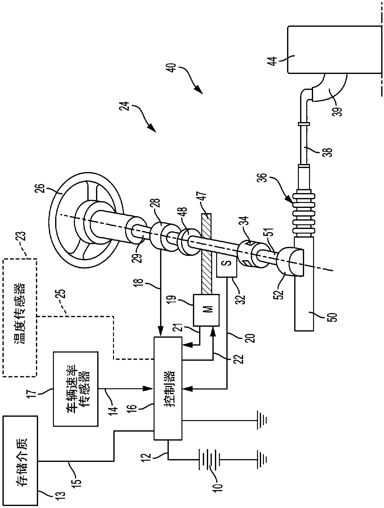
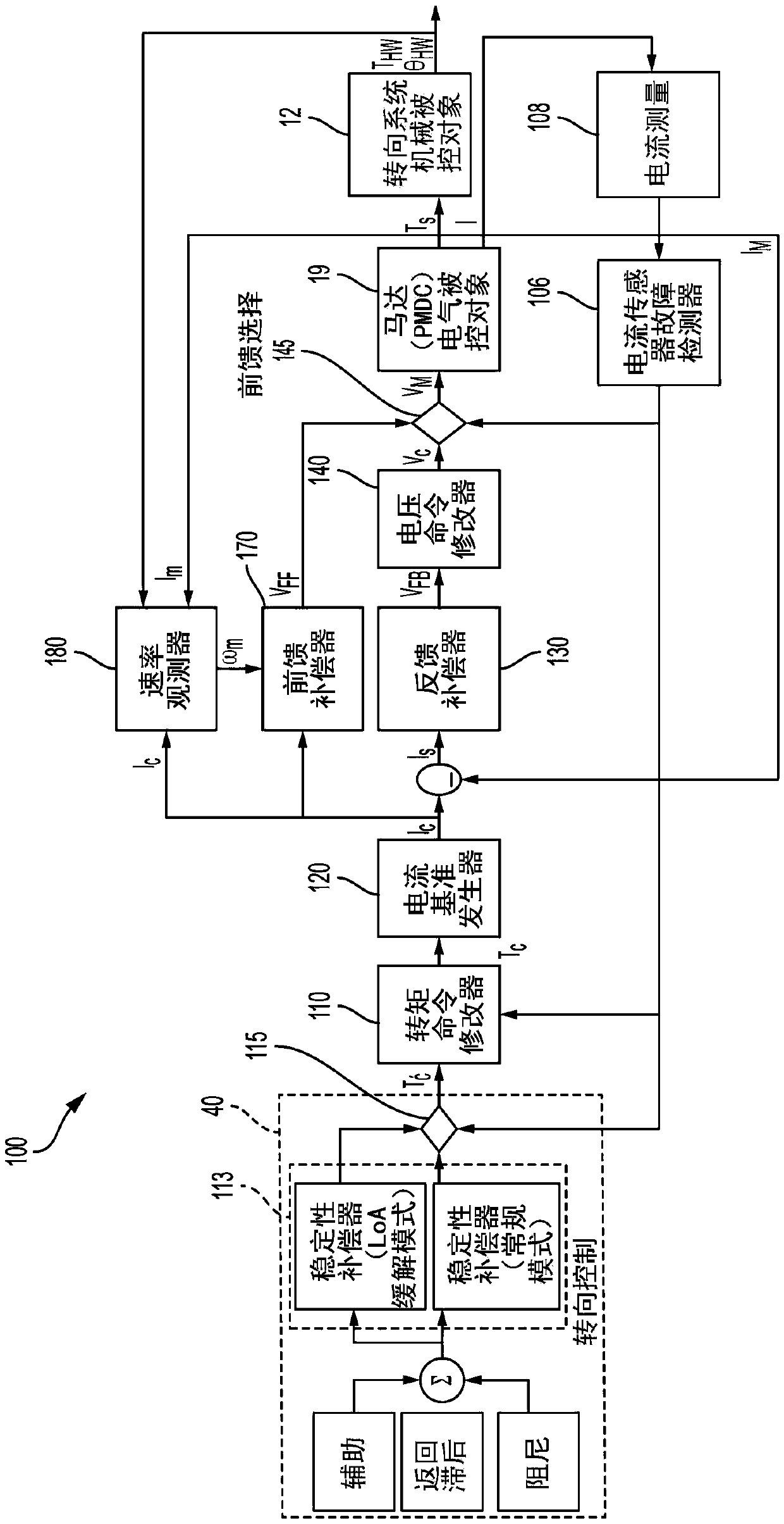
[0025] Referring now to the drawings, the technical solution will be described with reference to certain embodiments, rather than being limited thereto. figure 1 is an exemplary embodiment of an electric power steering system (EPS) 40 suitable for implementing the disclosed embodiments. Steering mechanism 36 is a rack and pinion system and includes a rack (not shown) located within housing 50 and a pinion (also not shown) located below gear housing 52 . As an operator input, hereinafter denoted as turning the steering wheel 26 (eg a hand-held steering whe...


PUM


Abstract

Technical solutions are described for current sensor fault mitigation for systems with permanent magnet DC drives. An example power steering system includes a brush motor, and a motor control system that generates an amount of torque using the brush motor, the amount of torque corresponding to a torque command. The motor control system includes a current sensor fault detector that detects a current sensor fault associated with a current sensor used to measure a current across the brush motor. The motor control system further includes a velocity observer that computes an estimated motor velocity in response to the current sensor fault. The motor control system further includes a feed forward controller that generates a current command for generating the amount of torque using the brush motor, the current command generated using the estimated motor velocity. The described technical solution solves the technical problem of current sensor fault mitigation of a EPS system based on PMDC drive.

Description

technical field [0001] The present application relates to steering systems, particularly Electric Power Steering (EPS) systems, and more particularly to fault mitigation techniques for motor control in the event of loss of current sensors in EPS driven using permanent magnet DC. Background technique [0002] Permanent magnet DC (PMDC) motors are widely used in motion control applications including EPS systems. Torque control of a PMDC motor drive is performed by current regulation using measured current feedback (through a current measurement circuit). Feedback current control performed in this manner provides adjustable current (and thus adjustable torque) control bandwidth characteristics, disturbance rejection, and less sensitivity to modeling uncertainties. Another advantage of using a PMDC motor drive with feedback control operation is that no position or speed measurement is required for control. It should be noted, however, that motor speed is an important signal to...

Claims


Application Information

Patent Timeline
Patent Type & Authority Applications(China)
IPC IPC(8): H02P21/18
CPCB62D5/0481H02P29/032B62D5/049H02P2205/01H02P7/285B62D5/046
Inventor P·普拉莫德R·密特拉R·拉马努贾姆
Owner STEERING SOLUTIONS IP HLDG
Why Eureka
Try Eureka