Water dispenser

A water dispenser and water source technology, applied in beverage preparation devices, household appliances, applications, etc., can solve the problems of complicated operation, complicated operation steps, residual smell of the water dispenser, etc., and achieve the effects of simple operation, good sterilization effect and simple structure

Pending Publication Date: 2019-05-17
FOSHAN SHUNDE MIDEA WATER DISPENSER MFG +1
View PDF0 Cites 3 Cited by
  • Summary
  • Abstract
  • Description
  • Claims
  • Application Information

AI Technical Summary

Problems solved by technology

The use of ozone sterilization needs to completely drain the remaining water in the pipeline of the water dispenser, then use a three-way pipe to connect the water inlet pipes of the cold and hot water channels of the water diversion pool, start the ozone generator, and let the ozone enter the water dispenser cold tank, hot tank and water dispenser The anti-virus is realized in the pipeline. On the one hand, the operation steps of this technology are relatively cumbersome. On the other hand, the water dispenser after cleaning has a pungent smell, and it needs to be rinsed several times to remove the odor.
The existing technology also uses water circulation to clean and flush the pipeline, but this cleaning process uses normal temperature water to flush, which cannot achieve a bactericidal effect
It also needs to be used with professional cleaning solvents. As we all know, any chemical agent cleaning is easy to leave residues, and a large amount of water must be repeated to remove the residues of drug agents.
The same adverse effect is that the operation is complicated and it is easy to cause drug residues, which is not conducive to healthy drinking water.

Method used


Image

  • Water dispenser
  • Water dispenser

Examples


Embodiment Construction

[0029] Embodiments of the present invention are described in detail below, examples of which are shown in the drawings, wherein the same or similar reference numerals designate the same or similar elements or elements having the same or similar functions throughout. The embodiments described below by referring to the figures are exemplary and are intended to explain the present invention and should not be construed as limiting the present invention.

[0030] In describing the present invention, it is to be understood that the terms "center", "upper", "lower", "vertical", "horizontal", "top", "bottom", "inner", "outer", The orientation or positional relationship indicated by "clockwise", "counterclockwise", etc. is based on the orientation or positional relationship shown in the drawings, and is only for the convenience of describing the present invention and simplifying the description, rather than indicating or implying the referred device or element Must be in a particular o...


PUM


Abstract

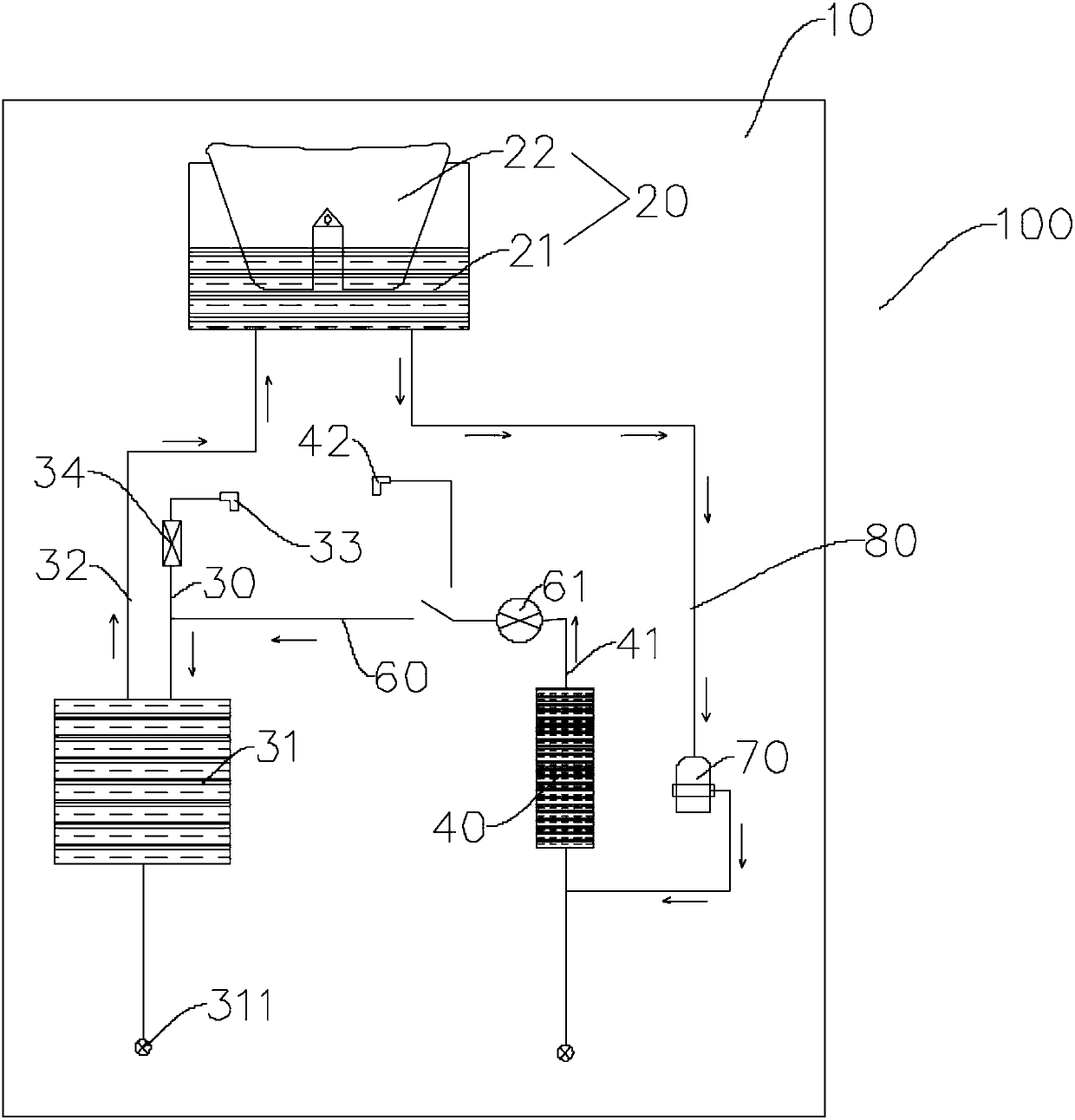
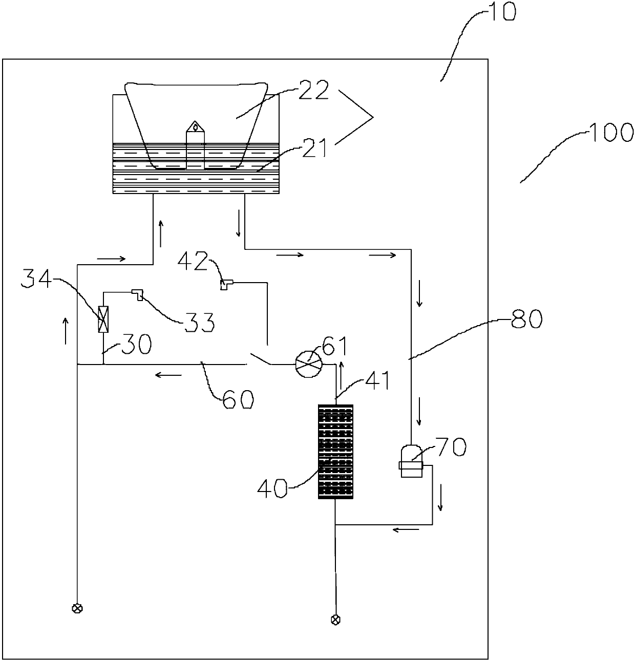
The invention discloses a water dispenser which comprises a machine body, a water source component, a cold water outlet pipeline, a hot water outlet pipeline, a heating part, a circulation water path,an electromagnetic valve and a pumping device, wherein the water source component is arranged on the machine body; one end of the hot water outlet pipeline is communicated with the water source component; the heating part is arranged on the hot water outlet pipeline to heat water passing through the hot water outlet pipeline; the circulation water path is arranged between the hot water outlet pipeline and the cold water outlet pipeline and connected with the hot water outlet pipeline and the cold water outlet pipeline respectively; the electromagnetic valve is arranged between the circulationwater path and the hot water outlet pipeline; the electromagnetic valve switches between a first state and a second state; when being at the first state, the electromagnetic valve is used for being communicated with a hot water outlet and the water source component; when being at the second state, the electromagnetic valve is used for being communicated with the hot water outlet pipeline and thecirculation water path; the pumping device is communicated with the water source component to circulate water in the water source component. The water dispenser disclosed by the embodiment of the invention is simple in structure and has a good sterilization effect.

Description

technical field [0001] The present invention relates to the technical field of home appliances, and more specifically, to a water dispenser. Background technique [0002] At present, most of the water dispensers on the market usually put the barrel neck of the bottled water upside down and put it on the "smart seat" of the water dispenser, and then the hose inside the machine guides the water into two water tanks, one of which is hot water Two gallbladders, one is a cold water gallbladder, these two water gallbladders can not only produce cold and hot water, but also precipitate impurities in the water. People usually change the bottled water repeatedly, but they ignore that there is still a certain amount of water in the inner tank of the water dispenser, which will hide pathogenic bacteria. Over time, it will naturally become a breeding ground for bacteria. Consumers often have such misunderstandings that the water dispenser itself is a water purification device, and the ...

Claims


Application Information

Patent Timeline
Patent Type & Authority Applications(China)
IPC IPC(8): A47J31/60A47J31/00
Inventor 阮涛
Owner FOSHAN SHUNDE MIDEA WATER DISPENSER MFG
Why Eureka
Try Eureka