Vertical photocatalytic oxidation device with drainage water discharge function
A photocatalytic oxidation, vertical technology, applied in the direction of chemical instruments and methods, dispersed particle separation, separation methods, etc., can solve the problems of emission concentration adjustment, reaction rate adjustment, energy waste, etc., to ensure normal use and improve the effect , Ease of use
- Summary
- Abstract
- Description
- Claims
- Application Information
AI Technical Summary
Problems solved by technology
Method used
Image
Examples
Embodiment 1
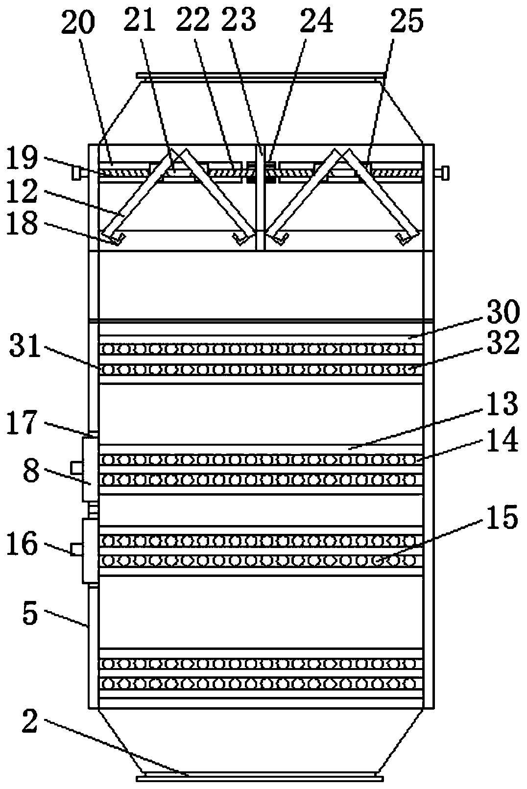
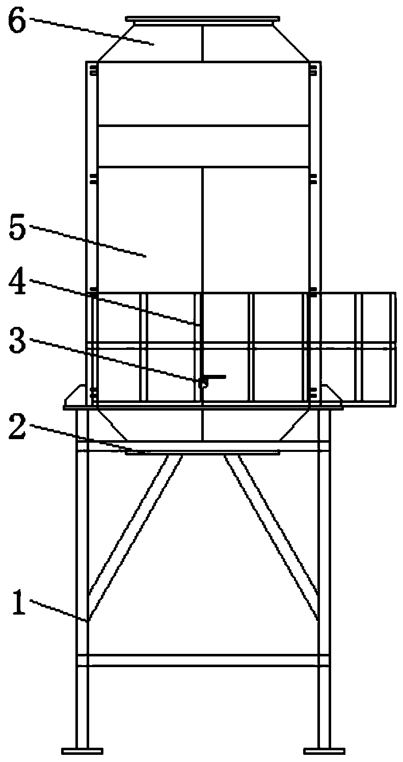
[0028] Example 1, such as Figure 1-7: Turn on the power supply, the first lamp tube 15 and the second lamp tube 32 light up at the same time, and the ultraviolet light is irradiated on the nano-TiO2 catalyst on the first photocatalyst plate 13 and the second photocatalyst plate 30, and the nano-TiO2 catalyst absorbs light energy to generate electrons Leap forward and hole leap forward, through further combination to generate electron-hole pairs, react with moisture (H2O) and oxygen (O2) adsorbed on the surface of exhaust gas to generate highly oxidative hydroxyl radicals and superoxide ion radicals Various organic waste gases such as hydrocarbons, aldehydes, phenols, alcohols, mercaptans, benzene, ammonia, nitrogen oxides, sulfides and other VOC organic and inorganic substances are reduced to carbon dioxide under the action of photocatalytic oxidation (CO2), water (H2O) and other non-toxic and harmless substances, after purification, the exhaust gas molecules are activated an...
Embodiment 2
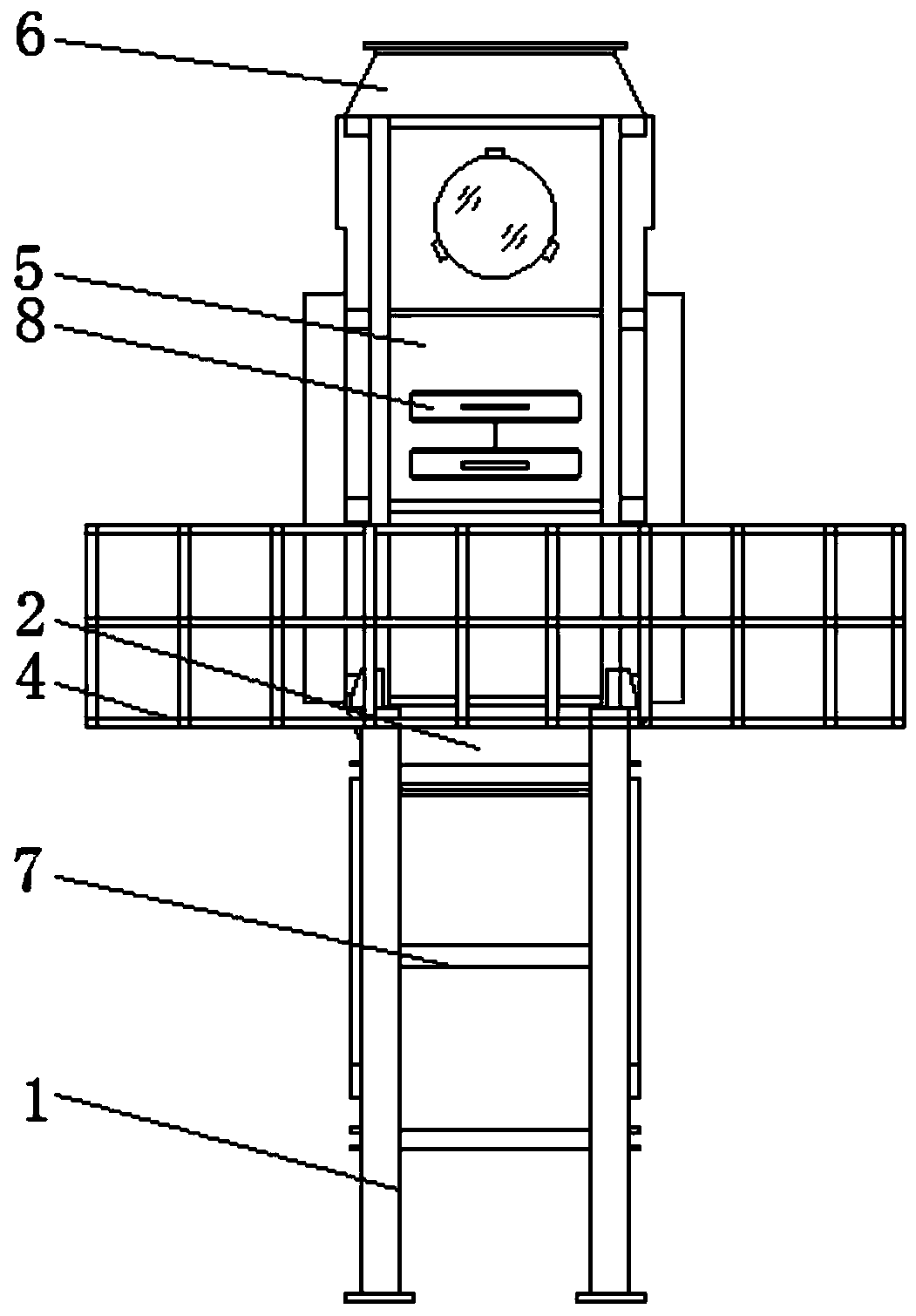
[0029] Example 2, such as figure 1 , 3 , 5, 6, 8: Pull the pumping plate 8 through the pull rod 16, pull out the first lamp board 14 on the pumping plate 8 from the inside of the housing 5, and then seal the through groove 17, the second lamp board 14 inside the housing 5 Since the photocatalyst plate 30 is not irradiated by ultraviolet light, the photocatalytic oxidation reaction does not proceed.
Embodiment 3
[0030] Example 3, such as figure 1 , 5 , 7: Turn the knob on the rotating rod 21 to drive the positive thread 19 and the reverse thread 22 on the rotating rod 21 to rotate at the same time, because the rotating rod 21 runs through the first slider 25, and the inside of the first slider 25 is provided with threads hole, so the rotation of the rotating rod 21 drives the first slider 25 to move in the same direction inside the first chute 20, and since the first slider 25 is connected with the second slider 26 through the connecting rod 28, the second slider 25 The movement of a slider 25 drives the second slider 26 to move inside the second chute 27, and at the same time drives the baffles 12 to deflect, shortening the distance between the two groups of baffles 12, reducing the rate of gas discharge, and prolonging the discharge time of the exhaust gas. The residence time inside the shell 5 ensures the thorough progress of the catalytic reaction.
[0031] Working principle: Be...
PUM
 Abstract
Description
Claims
Application Information
 - R&D
- Intellectual Property
- Life Sciences
- Materials
- Tech Scout
- Unparalleled Data Quality
- Higher Quality Content
- 60% Fewer Hallucinations
Browse by: Latest US Patents, China's latest patents, Technical Efficacy Thesaurus, Application Domain, Technology Topic, Popular Technical Reports.
© 2025 PatSnap. All rights reserved.Legal|Privacy policy|Modern Slavery Act Transparency Statement|Sitemap|About US| Contact US: help@patsnap.com


