Hydraulic vice

A vise, hydraulic technology, applied in the direction of clamping, supporting, positioning device, etc., can solve the problems of uncompact structure, small force multiplier, low work efficiency, etc., achieve simple and compact overall structure, improve matching accuracy, clamping Efficient effect

Active Publication Date: 2019-05-17
HENAN UNIV OF SCI & TECH
View PDF7 Cites 3 Cited by
  • Summary
  • Abstract
  • Description
  • Claims
  • Application Information

AI Technical Summary

Problems solved by technology

[0003] The currently widely used vise is a vise that is powered by a screw, that is, the movable jaw moves back and forth under the transmission of the screw, and cooperates with the fixed jaw to clamp and fix the workpiece; this mechanical vise The structure is simple, but it is cumbersome to use. It needs to shake the screw repeatedly to open and close the jaws, which is labor-intensive and low-efficiency.
[0004] The Chinese patent with application number 201420555283.1 discloses a hydraulic vise vise, which expands the rubber sleeve to clamp the pipe by injecting hydraulic oil into the hollow rubber sleeve, and adjusts the stroke of the hydraulic cylinder to drive the slider to clamp the pipe. The clamping is realized by the expansion of the rubber sleeve, resulting in small clamping force and small application range; and the main part of the vise is separated from the hydraulic source, resulting in an uncompact structure and complicated operation
The patent with the application number 201610240681.8 discloses a multi-purpose hydraulic vise. By rotating the pre-clamping screw, the movable vise moves forward; The plunger of the center plunger pump produces high-pressure oil, thereby pushing the plunger rods of the two clamps to move to realize the clamping of the workpiece; a fixed baffle with a hanging foot assembly is set to overcome the limitation of the stroke of the pre-clamping screw; when working , first install the hanging foot assembly according to the needs, then place the workpiece against the baffle, and then realize the pre-tightening and tightening process of the workpiece; the hydraulic vise also has the defects of complicated operation process, high labor intensity and low efficiency

Method used


Image

  • Hydraulic vice
  • Hydraulic vice
  • Hydraulic vice

Examples


Embodiment Construction

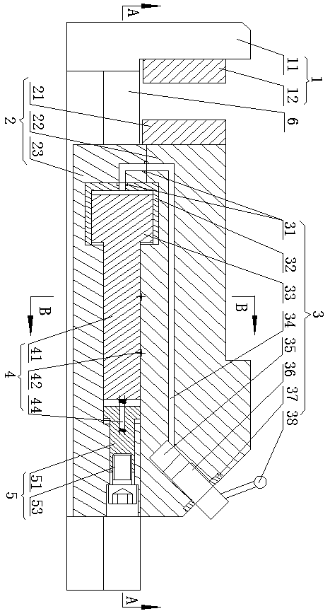
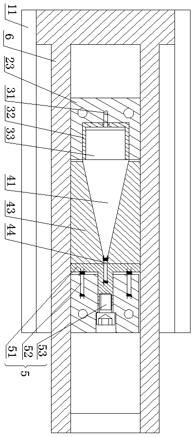
[0032] In the description of the embodiments of the present invention, it should be understood that the orientations or positional relationships indicated by the terms "up", "down", "left", "right" etc. are based on the attached figure 1 The orientations or positional relationships shown are only for the convenience of describing the present invention and simplifying the description, and do not indicate or imply that the referred device or element must have a specific orientation, be constructed and operated in a specific orientation, and therefore cannot be construed as an important aspect of the present invention. Limitation of Scope of Protection. define at the same time figure 1 The position of each part or mechanism is the original position, and the movement direction of each part or mechanism is figure 1 direction shown, figure 2 The shown movement of the limiting block 43 toward the center of the guide rail is inward movement, and the movement away from the center of...


PUM


Abstract

The invention discloses a hydraulic vice. The hydraulic vice comprises an L-shaped fixed vice body, a guide rail integrally arranged on a horizontal part of the fixed vice body, a movable vice body capable of moving back and forth along the guide rail, a hydraulic system, a locking mechanism and a limiting mechanism; the hydraulic system comprises a pressure applying mechanism and a hydraulic cylinder connected with the pressure applying mechanism; the locking mechanism comprises a pressure transfer device connected with a working plunger, and limiting blocks which can move towards the side wall of the guide rail and form a combing structure with the guide rail; in the pressurizing initial stage, the pressure transfer device is pushed by the working plunger to move rightwards, and the limiting blocks move towards the corresponding side walls of the guide rail under action of the limiting mechanism till the limiting blocks are combined with the guide rail so that locking of the lockingmechanism and the fixed vice body can be achieved; pressurizing continues, the hydraulic cylinder is made to do reverse motion relative to the working plunger and drives the movable vice body to clampa workpiece. According to the hydraulic vice, through the hydraulic system, the locking mechanism and the limiting mechanism which are arranged in an interactional mode, the movable vice body is pushed to move, the whole structure is simple and compact, the clamping force is large, and the clamping efficiency is high.

Description

technical field [0001] The invention relates to the technical field of clamping tools, in particular to a hydraulic vise. Background technique [0002] Bench vise is a kind of clamping tool commonly used in machinery manufacturing. It is a random accessory of machine tools such as milling machines and drilling machines. It is fixed on the machine tool table to clamp the workpiece for cutting processing; to hold the workpiece. [0003] The currently widely used vise is a vise that is powered by a screw, that is, the movable jaw moves back and forth under the transmission of the screw, and cooperates with the fixed jaw to clamp and fix the workpiece; this mechanical vise The structure is simple, but it is cumbersome to use. It is necessary to repeatedly shake the screw to open and close the jaws, which is labor-intensive and low-efficiency. [0004] The Chinese patent with application number 201420555283.1 discloses a hydraulic vise vise, which expands the rubber sleeve to c...

Claims


Application Information

Patent Timeline
Patent Type & Authority Applications(China)
IPC IPC(8): B23Q3/08
Inventor 杨茜杨永顺
Owner HENAN UNIV OF SCI & TECH
Why Eureka
Try Eureka