
Accelerometer chip and processing technology and accelerometer based on qos technology

An accelerometer and processing technology, applied in the direction of measuring acceleration, speed/acceleration/shock measurement, instruments, etc., can solve the problems of accelerometer accuracy and stability, low accuracy of quartz wet corrosion, and reducing the effect of differential motion, etc. , to achieve the effect of low cost, high precision dry etching and high precision

Active Publication Date: 2020-03-17
XI AN JIAOTONG UNIV
View PDF14 Cites 0 Cited by
  • Summary
  • Abstract
  • Description
  • Claims
  • Application Information

AI Technical Summary

Problems solved by technology

The disadvantages of this method are: the precision of quartz wet etching is low, and it is difficult to make the structure smaller; secondly, micro-assembly after independent processing will introduce assembly errors. The state of the root vibrating beam is exactly the same, and there is often a large difference between the two beams due to pasting, which greatly reduces the effect of differential motion, and impurities such as water vapor in the glue will also affect the accuracy and stability of the accelerometer. In addition, due to the large difference in the thermal expansion coefficients of the two materials in the chip obtained by the split processing method, when the external environment temperature changes, thermal stress occurs in the axial direction of the quartz vibration beam, resulting in temperature drift of the accelerometer output

Method used


Image

  • Accelerometer chip and processing technology and accelerometer based on qos technology
  • Accelerometer chip and processing technology and accelerometer based on qos technology
  • Accelerometer chip and processing technology and accelerometer based on qos technology

Examples


Embodiment Construction

[0034] The present invention will be further described in detail below with reference to specific examples, which are to explain rather than limit the present invention.

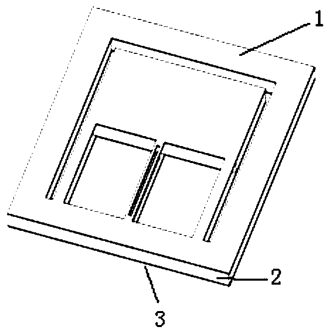
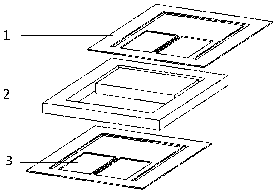
[0035] refer to figure 1 and 2 , Z-direction sensitive quartz vibrating beam accelerometer chip based on QoS process, including first quartz structure 1, silicon-based structure 2 and second quartz structure 3 in order from top to bottom, first quartz structure 1 and silicon-based structure 2 and silicon The base structure 2 and the second quartz structure 3 are both bonded and connected, and the first quartz structure 1 and the second quartz structure 3 have the same structure. The typical thickness of the first quartz structure 1 is 10-50 μm, which can be flexibly changed according to design and process requirements.

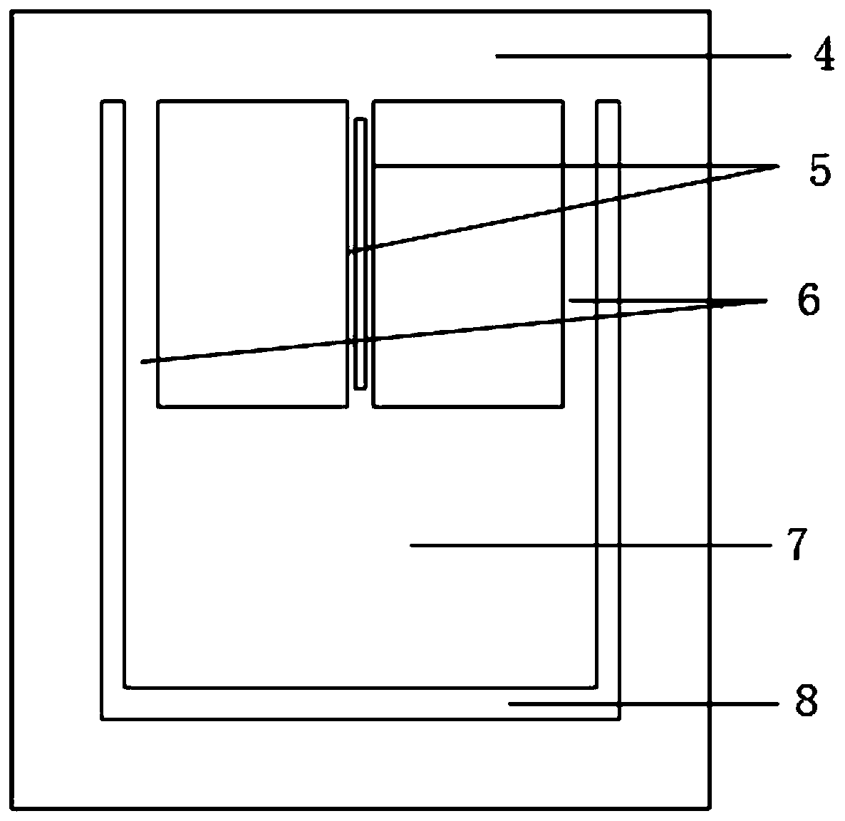
[0036] refer to image 3 The first quartz structure 1 includes a quartz frame 4, a double-ended fixed quartz tuning fork 5, a quartz support beam 6 and a quartz mass block 7; the quartz f...


PUM

PropertyMeasurementUnit
thicknessaaaaaaaaaa
thicknessaaaaaaaaaa

Abstract

The invention provides a chip of a Z-direction sensitive quartz vibration beam accelerometer based on a quartz on silicon (QoS) technology, a processing technology and an accelerometer. The chip comprises a first quartz structure and a second quartz structure, wherein the first quartz structure and the second quartz structure are bonded on two sides of a silicon substrate structure; the quartz structures comprise quartz frames, two-end fixed quartz tuning forks, quartz supporting beams and quartz mas blocks; the silicon substrate structure comprises a silicon substrate frame and a silicon massblock; a sandwich form of the first quartz structure, the silicon substrate structure and the second quartz structure is formed and completely bonded at the quartz frame and the silicon substrate frame and the quartz mass block and the silicon mass block; and the processing technology comprises the steps that firstly, initial processing of the silicon substrate is carried out, then double-surfacebonding of the silicon substrate and two quartz pieces is carried out, the two quartz pieces are subjected to thinning and polishing, then quartz vibration beam electrodes and the quartz structures are manufactured, and finally the silicon substrate structure is released. The chip of the Z-direction sensitive quartz vibration beam accelerometer has the characteristics that the sensitivity is high, the cost is low and the like.

Description

technical field [0001] The invention belongs to the technical field of micro-mechanical electronics (MEMS) digital accelerometers, in particular to a Z-direction sensitive quartz vibrating beam accelerometer chip based on QoS (Quartz on Silicon) technology, a processing technology and an accelerometer. Background technique [0002] The traditional quartz vibrating beam accelerometer is limited by the quartz processing technology, and can only use the wet etching process to realize the processing of the integrated quartz structure, and the wet etching has poor precision control, and it is difficult to achieve the precision of miniaturized high-precision complex structures. Reliable machining. Another solution is to use a split structure in which the quartz vibrating beam is combined with other base materials. The quartz vibrating beam is used as a sensitive element, and other base materials are used to process elastic elements. Commonly used base materials include silicon and...

Claims


Application Information

Patent Timeline
Patent Type & Authority Patents(China)
IPC IPC(8): G01P15/097
Inventor 李村韩超赵玉龙李波张全伟白冰
Owner XI AN JIAOTONG UNIV
Learn More