Cutter handle capable of realizing composition of ultrasonic vibration and low-frequency vibration
A low-frequency vibration and ultrasonic vibration technology, which is applied to the parts of grinding machine tools, metal processing equipment, grinding/polishing equipment, etc., can solve the problems of limitations and inability to realize non-rotary tool-driven processing of superhard abrasives, and achieve stable operation Effect
- Summary
- Abstract
- Description
- Claims
- Application Information
AI Technical Summary
Problems solved by technology
Method used
Image

Examples
Embodiment Construction
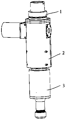
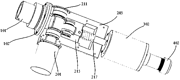
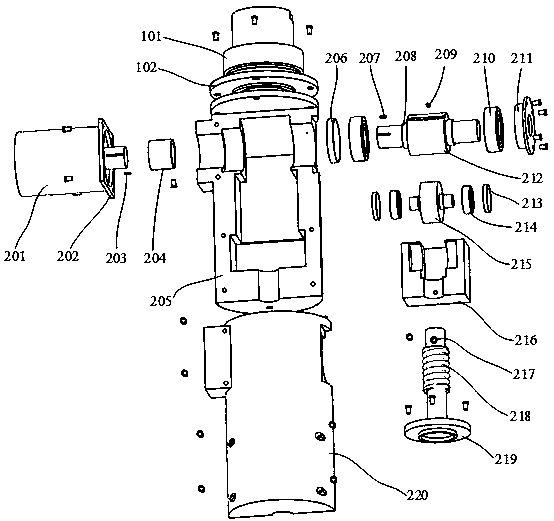
[0021] exist Figure 1-4 In the shown embodiment, it includes three parts: a handle part 1 , a low-frequency mechanical vibration part 2 and an ultrasonic vibration part 3 . The tool handle part 1 is rigidly matched with the low-frequency vibration part 2 through the flange 102 and the screw, and the two parts are guaranteed to be on the same axis; the low-frequency mechanical vibration part 2 is protected by the flange at the lower end of the low-frequency vibration shaft 219 and the ultrasonic part 3 The cover is matched and fastened by screws; the end of the horn 305 of the ultrasonic part 3 is provided with threads and cavities, which cooperate with the standard ER collet to realize tool clamping. The center lines of the three parts are based on the center of the HSK standard interface 101 and coincide with it. The standard interface 101 of the handle part 1 and the flange 102 are integrated, the HSK standard interface 101 at the upper end is used to connect with the spin...
PUM
 Abstract
Description
Claims
Application Information