Active pressure building mechanism

An active and hydraulic technology, applied in the direction of brakes, electromechanical devices, structural connections, etc., can solve the problems of heavy weight, large space occupation, low integration, etc., achieve fast response speed of pressure building, shorten axial distance, and smaller space the effect of

Inactive Publication Date: 2019-05-21
LIANCHUANG AUTOMOBILE ELECTRONICS +1
View PDF4 Cites 4 Cited by
  • Summary
  • Abstract
  • Description
  • Claims
  • Application Information

AI Technical Summary

Problems solved by technology

A few developed active pressure building mechanisms that use permanent magnet motors connected to transmission mechanisms, such as active pressure building mechanisms driven by motors to drive worm gears and ball screws, etc., have a long axial connection length of the overall structure, occupy a large space, and have complicated parts
The reason is that, first of all, the current drive motor rotors adopt a solid structure, which is heavy and has a large moment of inertia; secondly, there needs to be enough installation space for the motor position sensor inside the motor, such as the reluctance type resolver with better performance. It is also necessary to provide enough layout space for its stator assembly inside the motor, resulting in a large overall volume of the motor and restrictions on its structural design; finally, the output structure of the motor is connected to the external transmission mechanism to realize the pressure build-up of the driving master cylinder piston
This results in a large volume of the overall active pressure building mechanism, complex structural connections, low integration, and slow response.

Method used


Image

  • Active pressure building mechanism
  • Active pressure building mechanism

Examples


Embodiment Construction

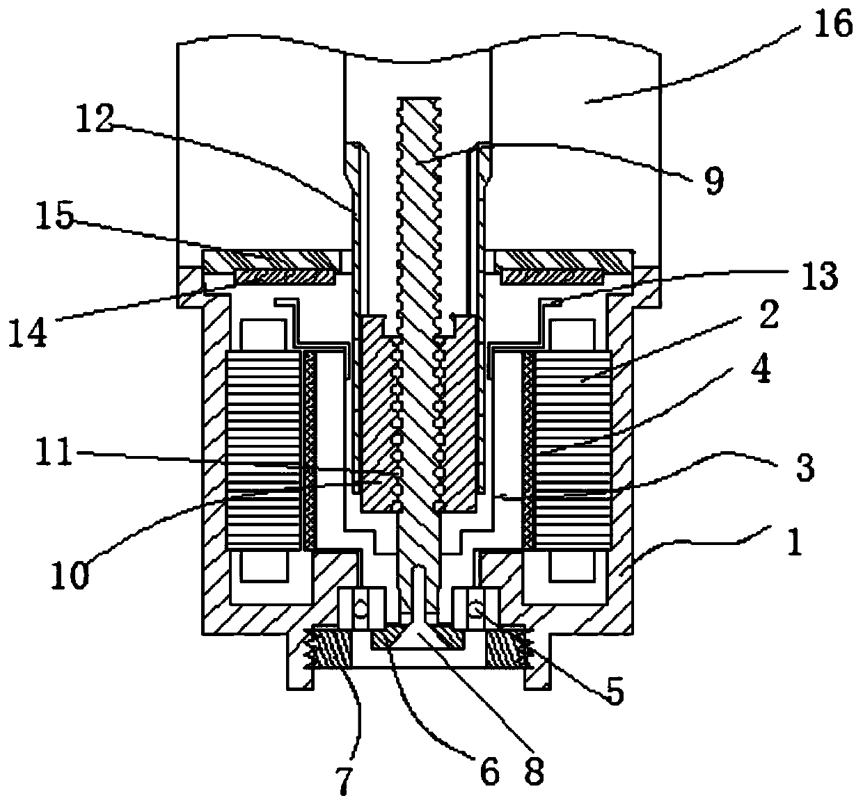
[0049] Such as figure 1As shown, the present invention provides an active pressure building mechanism for an electro-hydraulic braking system, including: a housing 1, a motor stator 2, a motor hollow rotor 3, a permanent magnet 4, a bearing 5, a gasket 6, and a lock nut 7. Screw 8, screw rod 9, follower 10, ball 11, anti-rotation hollow tube 12, sensor rotor 13, sensor stator 14, sensor stator support 15, hydraulic control unit 16;

[0050] The bottom of the hydraulic control unit 16 has a hole for fixing the sensor stator support 15 , and the bottom end is connected with the first opening of the housing 1 . The sensor stator 14 is fixed under the sensor stator support 15, the screw mandrel 9, the follower 10 and the anti-rotation hollow tube 12 are inserted into the hydraulic control unit 16 through the through holes on the sensor stator support 15 and the sensor stator, and the lower port of the housing 1 is formed Stepped inner hole, the upper end of the outer ring of the ...


PUM


Abstract

The invention discloses an active pressure building mechanism. According to the active pressure building mechanism, a hydraulic control unit is connected with a motor shell, the bottom face of the hydraulic control unit is provided with a sensor stator supporting piece and a sensor stator, a screw rod, a driven piece and an anti-rotation piece are inserted into the hydraulic control unit via through holes in the sensor stator supporting piece and sensor stator, a bearing is locked on the shell through a second connecting piece, a first connecting piece is fixedly clamped by the bearing, the upper portion of the anti-rotation piece is inserted into the hydraulic control unit and fixed in the hydraulic control unit, the lower portion of the anti-rotation piece is inserted into a hollow rotorof a motor, the driven piece is fixed in the anti-rotation piece, the driven piece is connected with the penetrating screw rod through a transmission piece, a sensor rotor and the hollow rotor of themotor are located under the sensor stator, the bottom of the hollow rotor of the motor is provided with a stepped shaft, a third connecting piece penetrates through the first connecting piece and thehollow rotor of the motor and then is connected with the bottom face of the screw rod, and a tapered surface cooperating with the tapered bottom face of the hollow rotor of the motor is formed on thebottom of the screw rod. Compared with the prior art, the active pressure building mechanism has the advantages that the weight is lower, the inertia moment is smaller, the size is smaller, and the integration level is higher.

Description

technical field [0001] The invention relates to the field of automobiles, in particular to an active pressure building mechanism for an electronic hydraulic braking system. Background technique [0002] With the development of vehicle intelligence and electrification, the traditional braking system loses the vacuum boosting function due to the lack of vacuum power source, while the improved device has a large structure and complex system. Compared with the traditional vacuum booster, the electro-hydraulic braking system has quick response, high pressure build-up, and has functions such as active braking and regenerative braking. Therefore, the electronic hydraulic braking system develops rapidly and becomes the trend of vehicle braking today. [0003] The electronic hydraulic braking system uses electronic components to replace some mechanical components, and its important component mechanism is the active pressure building mechanism, which is the source of power for the br...

Claims


Application Information

Patent Timeline
Patent Type & Authority Applications(China)
IPC IPC(8): B60T13/74H02K7/06H02K11/21
Inventor 刘宏慈赵锦艳臧洪元
Owner LIANCHUANG AUTOMOBILE ELECTRONICS
Why Eureka
Try Eureka