Motion distance testing and limiting device for lifting equipment

A technology of moving distance and testing device, applied in the direction of measuring device, transportation and packaging, instruments, etc., can solve the problems of complex adjustment process, deterioration of adjustment accuracy, poor adjustment accuracy of limit travel switch, etc., to achieve flexible parameter setting, improve Reliability and precision, simple adjustment effect

Pending Publication Date: 2019-05-21
浙江东川自动化科技有限公司
View PDF6 Cites 1 Cited by
  • Summary
  • Abstract
  • Description
  • Claims
  • Application Information

AI Technical Summary

Problems solved by technology

[0004] In the hoisting equipment system, every time the steel wire rope is replaced, the position of the cam set of the limit travel switch needs to be readjusted. Due to the poor adjustment accuracy of the limit travel switch, especially after passing through the reducer, the adjustment accuracy is even worse. In the actual use process, repeated adjustments are required, the adjustment process is extremely complicated, and the effect is not satisfactory, resulting in poor use of the limit travel switch

Method used


Image

  • Motion distance testing and limiting device for lifting equipment
  • Motion distance testing and limiting device for lifting equipment
  • Motion distance testing and limiting device for lifting equipment

Examples


specific Embodiment approach 1

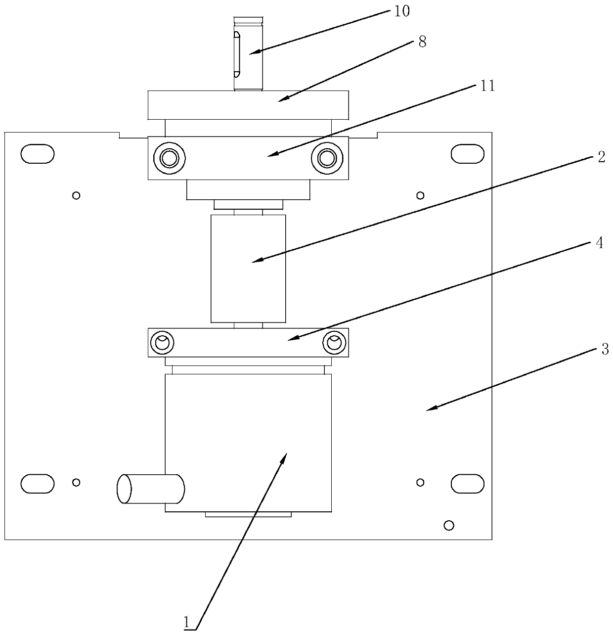
[0051] A lifting equipment system of the present application, such as figure 1 As shown, it includes a drive shaft 10, a flange 8, a coupling 2, a rotary encoder 1, a positioning block 11, a rotary encoder mounting block 4, and a mounting plate 3. The positioning block 11 and the rotary encoder mounting block 4 are installed On the mounting plate 3, the flange 8 is mounted on the positioning block 11, the transmission shaft 10 is fixedly connected to one end of the coupling 2 through the center hole of the flange 8, and the other end of the coupling 2 is connected to the rotary encoder 1, and the rotation The encoder 1 is fixedly installed on the rotary encoder mounting block 4 .

[0052] In the hoisting equipment system, the transmission shaft 10 is connected to the wire rope drum, and every time the transmission shaft 10 rotates one turn, the wire rope drum correspondingly rotates one turn or at a corresponding angle. For the convenience of explanation, this application set...

specific Embodiment approach 2

[0059] Compared with the specific draft method 1, the lifting device also includes a controller, which is used to calculate the movement distance of the lifting device according to the encoding record of the rotary encoder, and output a control signal to control the movement of the lifting device according to the set threshold .

[0060] Because the movement of the hook head of the lifting equipment will shake during the movement, in order to make the calculation more accurate, the controller needs to correct the test data of the movement distance.

[0061] In a specific embodiment of the present application, the correction method adopts the median filter algorithm, and the specific correction method is as follows:

[0062] Taking the length of the sampling data window as L, the calculation method for the correction distance s1(t) of the hook head movement at a certain moment is as follows:

[0063] S1. Arranging the L numbers of s(t-L+1)~s(t) in ascending order;

[0064] S2...

specific Embodiment approach 3

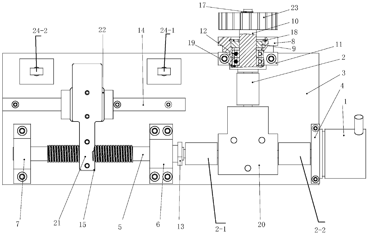
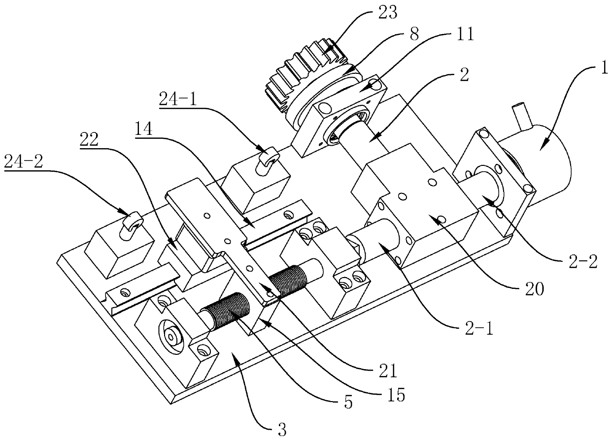
[0093] A hoisting equipment movement distance test and limit device of the present application, such as figure 2 , 3 shown, where image 3 yes figure 2 The three-dimensional structure, on the basis of the specific embodiment one, also includes a commutator 20, a displacement device, and a limit sensor. The commutator 20 is used to convert the rotation direction of the shaft coupling, such as converting the rotation in the vertical direction for horizontal rotation.

[0094] The shifting device is used to move correspondingly according to the rotation of the coupling, and to record the relative movement of the lifting equipment. The limit sensor is used to sense the position of the shifting device, and output the corresponding control when reaching the limited position signal to control the lifting equipment to work, the moving device is connected to one end of the commutator, and the other end of the commutator is connected to a shaft coupling.

[0095] Specifically, the...


PUM


Abstract

The invention discloses a motion distance testing and limiting device for lifting equipment. The testing device comprises an input gear, a rotary shaft, a shaft coupler and a rotary coder, wherein theinput gear is fixedly arranged on the rotary shaft; one end of the shaft coupler is connected with the rotary shaft, and the other end of the shaft coupler is connected with the rotary coder; the rotary coder records rotation of the input gear, and calculates the motion distance of the lifting equipment; the limiting device comprises a reverser, a shifting device and a limiting sensor, wherein the reverser is used for converting the rotation direction of the shaft coupler; the shifting device is used for recording relative movement of the lifting equipment; and the limiting sensor outputs a corresponding control signal while reaching a limiting position so as to control the lifting equipment to work. The rotary coder is adopted to realize testing and limiting the motion distance of the lifting equipment; and a mechanical limiting device is further arranged to realize dual limiting control on the lifting equipment, so that limiting can be guaranteed to realize, and collision of the lifting equipment is reduced.

Description

technical field [0001] The invention relates to the technical field of hoisting equipment, in particular to a movement distance test and limit device for hoisting equipment. Background technique [0002] The lifting equipment system is an extremely important equipment in the crane industry, and its performance is related to the safety of personnel and equipment. In actual use, the equipment needs to operate reliably at two positions, namely the upper limit and the lower limit, especially the upper limit. If the operation is not stopped at the upper limit, the lifting equipment will fall, causing serious accidents and damaging the equipment. , and even threaten personnel safety. [0003] The current hoisting equipment system mainly uses limit travel switches for position control. The limit switch is a control system composed of the main shaft through the gear reduction system, the camshaft with an adjustable cam set combination, and the micro switches arranged symmetrically...

Claims


Application Information

Patent Timeline
Patent Type & Authority Applications(China)
IPC IPC(8): B66C13/16B66C13/48B66C13/44B66C13/22B66C13/50G01B21/16
Inventor 邓小君吴巧
Owner 浙江东川自动化科技有限公司
Why Eureka
Try Eureka