Independent hydraulic wheel brake

A technology of hydraulic wheels and brakes, applied in the direction of brake types, axial brakes, brake actuators, etc., can solve problems such as unsealable, difficult air exhaust, and danger of host equipment, so as to avoid oil stagnation, The effect of eliminating leakage and simplifying work difficulty

Pending Publication Date: 2019-05-21
湖南三占科技股份有限公司
View PDF0 Cites 2 Cited by
  • Summary
  • Abstract
  • Description
  • Claims
  • Application Information

AI Technical Summary

Problems solved by technology

[0003] (1) The hydraulic pipeline between the hydraulic station and each oil cylinder is long, with many joints, a large amount of construction, and high requirements. Due to operational reasons or aging reasons, there is a high risk of leakage
The pipe is too long, and the air needs to be exhausted one by one, which makes it difficult to exhaust the air
[0004] (2) In the form of one-to-many components, if one of the oil cylinders has a leakage failure, the oil pressure will not be maintained, and it may cause all the wheel brakes driven by this hydraulic station to fail.
[0005] If the hydraulic station fails, a large area of ​​wheel brakes will fail immediately, which is very dangerous for a host device
[0006] (3) During long-term use, since the pipeline is long and the oil cylinders are all single-acting cylinders, the oil in the oil pipe cannot be renewed, and the oil in the oil cylinder will be faster because it does not participate in the circulation. Aging, the slow immersion of surrounding environmental media such as water, salt, acid and alkali components, etc. will cause oil quality to decline, which will aggravate the wear and tear of the oil cylinder, increase the possibility of rust, and seriously reduce the service life
[0007] (4) The traditional wheel brake cylinder is a single-acting cylinder. There is no hydraulic oil on the back of the piston (the side where the spring is installed), and the dust and grease in the middle will form sludge, which will be brought into the working area of ​​the piston, which will pollute the piston and cause the piston to Seal leaks
If the piston sealing ring leaks, all the hydraulic oil will leak to the spring side. Not only will the oil be lost, but also a vicious circle will be formed. Oil sludge further leads to poor sealing and greatly reduces the service life, and the failure rate is greatly increased
Leakage of the piston seal ring will also reduce the oil in the hydraulic system, and the leaked oil will also cause harm to the environment

Method used


Image

  • Independent hydraulic wheel brake
  • Independent hydraulic wheel brake
  • Independent hydraulic wheel brake

Examples


Embodiment 1

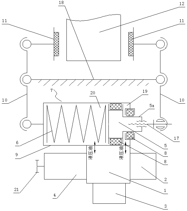
[0038] like Figure 1~2 As shown, an independent hydraulic wheel brake includes a pair of symmetrically arranged clamp arms 10, a pair of clamp seats 18, a symmetrically arranged pair of brake shoes 11, a valve block 1 with an internal oil passage, and a spring hydraulic cylinder 7 , The hydraulic pump 2 installed on the valve block 1, the hydraulic valve group 3 installed on the valve block 1. The hydraulic pump 2 is connected with the motor 4 . The motor 4 is provided with a hand wheel 21 coaxial with the output shaft of the motor.

[0039] The spring hydraulic cylinder 7 includes a hollow cylinder body 9 and a piston 5 arranged in the cylinder body 9 .

[0040] In the cylinder body 9, a pressure chamber 19 is provided on one side of the piston 5, a back pressure chamber 20 is provided on the other side of the piston 5, an oil inlet is provided at the pressure chamber 19, and an oil return port is provided at the back pressure chamber 20 , the oil passage of the valve blo...

Embodiment 2

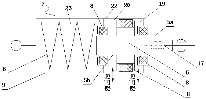
[0056] like image 3 As shown, Embodiment 1 is repeated, except that an oil barrier 22 is provided in the cylinder block 9 on the end face side of the piston 5 where the pressure end guide rod 5a is not provided. The cavity between the oil separating wall 22 and the end face of the piston where the pressure end guide rod 5 a is not provided is the back pressure cavity 20 . The oil separating wall 22 and the inner wall of the cylinder 9 on the side away from the piston 5 form a spring cavity 23 , and the spring 6 is located in the spring cavity 23 .

[0057] A back pressure end guide rod 5 b is provided on the end face of the piston 5 facing the back pressure chamber 20 , and the back pressure end guide rod 5 b can protrude into the spring cavity 23 through the oil separating wall 22 . One end of the spring 6 is fixedly connected with the end face of the cylinder 9 , and the other end is in contact with the end face of the back pressure end guide rod 5b. The contact part betw...


PUM


Abstract

The invention discloses an independent hydraulic wheel brake. The brake comprises clamp arms which are arranged symmetrically, a clamp base, brake shoes, a valve block, a spring hydraulic cylinder, ahydraulic pump and a hydraulic valve bank. The hydraulic pump is connected with the motor. A pressure cavity, a backpressure cavity, an oil inlet and an oil return port are formed in a spring hydraulic cylinder block. An oil way of the valve block communicates with the oil inlet and the oil return port in a butt-joint mode. A pressure end guide rod is arranged on one end surface of a piston and stretches out of one end of the cylinder block. A spring is arranged in the cylinder block, one end of the spring is fixedly connected with the end surface of the cylinder block, and the other end of the spring abuts against the end surface, where no pressure end guide rod is arranged, of the piston. One clamp arm is hinged to the pressure end guide rod, and the other clamp arm is hinged to the cylinder block. One end of the clamp base is hinged to one clamp arm, and the other end of the clamp base is hinged to the other clamp arm. The pair of brake shoes are hinged to the ends of the pair of clamp arms correspondingly. According to the independent hydraulic wheel brake, a highly integrated hydraulic driving mode is adopted, independent working is achieved, oil leakage is eliminated, and thesafety of main machine equipment is improved.

Description

technical field [0001] The invention relates to an independent hydraulic wheel brake, which is especially suitable for large-scale lifting equipment in ports. Background technique [0002] At present, the hydraulic wheel brakes used for large-scale lifting equipment in ports all use the form of one hydraulic station to drive several hydraulic wheel brake cylinders, that is, the so-called one-to-many. The hydraulic station and the oil cylinder are connected by oil pipes and joints. The existing structural forms have the following defects during use: [0003] (1) The hydraulic pipeline between the hydraulic station and each oil cylinder is long, with many joints, a large amount of construction, and high requirements. Due to operational reasons or aging reasons, there is a high risk of leakage. The pipes are too long, and the air needs to be exhausted one by one, which makes it difficult to exhaust the air. [0004] (2) In the one-to-many combination, if one of the oil cylin...

Claims


Application Information

Patent Timeline
Patent Type & Authority Applications(China)
IPC IPC(8): F16D55/225F16D65/14F16D121/04F16D125/02F16D125/04
Inventor 熊月华欧阳华生
Owner 湖南三占科技股份有限公司
Why Eureka
Try Eureka