
Energy router based on direct-current micro-grid inverter and load distribution control method of energy router

A technology of DC microgrid and DC power supply, applied in the field of electric power, can solve problems such as large voltage, power, fluctuation, etc., to achieve the effect of enhancing adaptability, strong controllability, and ensuring stable operation

Inactive Publication Date: 2019-05-21
SOUTHEAST UNIV
View PDF4 Cites 2 Cited by
  • Summary
  • Abstract
  • Description
  • Claims
  • Application Information

AI Technical Summary

Problems solved by technology

Although this method can accurately distribute the load, it will bring large voltage and power fluctuations

Method used


Image

  • Energy router based on direct-current micro-grid inverter and load distribution control method of energy router
  • Energy router based on direct-current micro-grid inverter and load distribution control method of energy router
  • Energy router based on direct-current micro-grid inverter and load distribution control method of energy router

Examples


Embodiment Construction

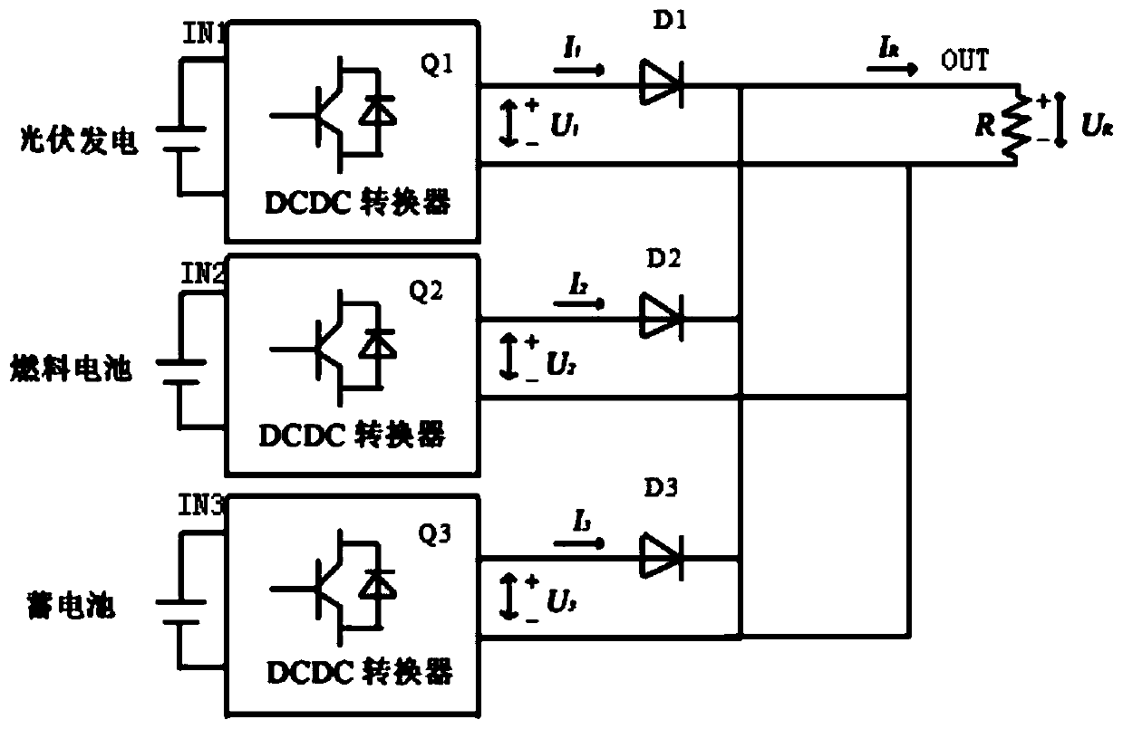
[0034] This embodiment provides an energy router based on a DC microgrid inverter, such as figure 1 As shown, it includes 3 input ports IN1, IN2, IN3, 3 buck-boost conversion circuits (BUCK-BOOST circuits) Q1, Q2, Q3, 3 diodes D1, D2, D3 and 1 output port OUT. The input end of the voltage conversion circuit Q1 is connected to the input port IN1, the high voltage end of the output end is connected in series with the diode D1, and the output end of the diode D1 is connected to the output port OUT, and the other branches are the same. When using the energy router, each input port can be connected to an external DC power supply, and the output port can be connected to an external DC bus. For example, in this embodiment, the input port IN1 is connected to a photovoltaic power generation device, and the input port IN2 is connected to a fuel cell. , connect the input port IN3 to the battery, and the output port OUT to the external DC bus UR. Understandably, the input port can also b...


PUM


Abstract

The invention discloses an energy router based on a direct-current micro-grid inverter and a load distribution control method of the energy router. The energy router comprises n input ports, n buck-boost conversion circuits, n diodes and one output port; n is a positive integer; the input end of each buck-boost conversion circuit is connected with one input port, and the output end of each buck-boost conversion circuit is connected with one diode in series; the output ends of all the diodes are all connected to the output port in parallel; and when in use, each input port is connected with anexternal direct-current power supply, and the output port is connected with an external direct-current bus. The energy router is simple in structure, easy to implement and higher in accuracy.

Description

technical field [0001] The invention relates to electric power technology, in particular to an energy router based on a DC microgrid inverter and a load distribution control method thereof. Background technique [0002] In recent years, in order to solve the problem of energy shortage and environmental pollution caused by the use of traditional fossil energy, the development and utilization of clean and non-polluting renewable energy such as solar energy and wind energy have been paid more and more attention, which will make the types of energy carriers more and more Diversification, the power system is likely to be connected to a variety of power sources. How to realize the input, output, conversion, and storage of different energy carriers, how to realize the interconnection and complementarity of different energy forms, and the organic connection between production and consumption have become problems that need to be solved. At the same time, because the traditional powe...

Claims


Application Information

Patent Timeline
Patent Type & Authority Applications(China)
IPC IPC(8): H02J1/10H02J7/35
CPCY02E10/56
Inventor 杨欣霈吴冰钰孙立
Owner SOUTHEAST UNIV
Learn More