DC motor speed-regulation device and method

The technology of a DC motor and speed regulating device is applied in the direction of DC motor speed/torque control, multiple motor speed adjustment, electrical components, etc., which can solve the problems of heavy pollution, damage to the power system, and increased energy consumption of the drilling drive system, etc. Achieve the effect of reducing costs, reducing drilling costs, and reducing transmission system losses

Inactive Publication Date: 2019-05-21
湖南鼎创装备有限公司
View PDF7 Cites 3 Cited by
  • Summary
  • Abstract
  • Description
  • Claims
  • Application Information

AI Technical Summary

Problems solved by technology

[0002] The original drilling platform uses two diesel engines as the power source to drive the actuators of the drilling platform through the transmission system. The diesel engine is noisy, pollutes heavily, requires a lot of maintenance, and consumes high energy. At the same time, the synchronization of the two diesel engines is poor, the speed regulation accuracy is low and there is no speed feedback, and the speed regulation needs to be adjusted through an external transmission system
The DC motor is now used as a new power source to replace the original diesel engine. The speed control of the DC motor is usually directly controlled by the governor, which is limited by the power of the governor, which greatly increases the cost.
[0003] Moreover, the existing DC motor speed control system applied to the drilling platform has no torque tracking system, and cannot change the torque output (such as drilling depth and rock) according to underground geological changes. Burning drill or power system damage

Method used


Image

  • DC motor speed-regulation device and method
  • DC motor speed-regulation device and method
  • DC motor speed-regulation device and method

Examples


Embodiment Construction

[0033] In order to make the object, technical solution and advantages of the present invention clearer, the present invention will be further described in detail below in conjunction with the accompanying drawings and embodiments. It should be understood that the specific embodiments described here are only used to explain the present invention, not to limit the present invention.

[0034] It should be noted that the orientation or positional relationship indicated by the terms "upper", "lower", "left", "right" and so on are based on the orientation or positional relationship shown in the drawings, and are only for convenience of description, rather than indicating or Implications that a referenced device or element must have a particular orientation, be constructed, and operate in a particular orientation should therefore not be construed as limiting the patent. The terms "first" and "second" are only used for descriptive purposes, and cannot be understood as indicating or im...


PUM


Abstract

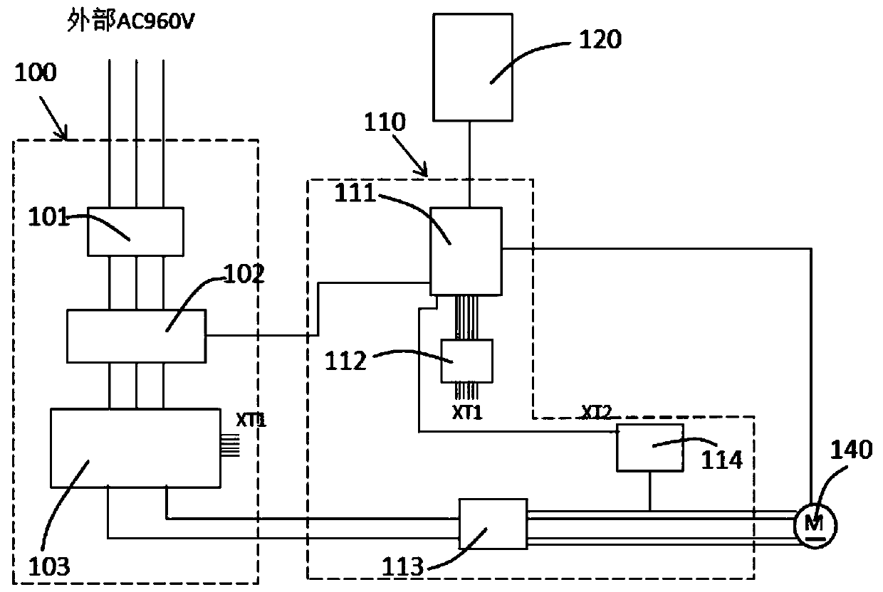
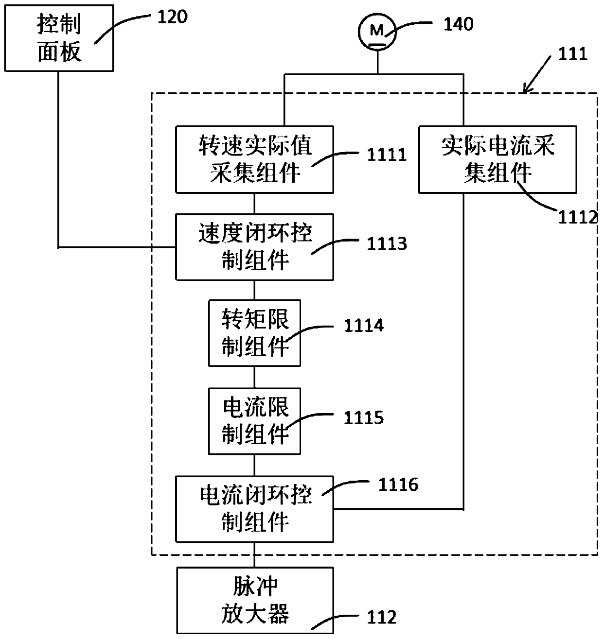
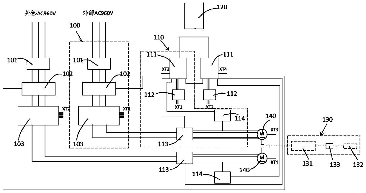
The invention discloses a DC motor speed-regulation device for a drilling platform. The device comprises a rectifier module including a thyristor; a control module including a DC speed regulator and apulse amplifier, wherein one end of the pulse amplifier is connected with the DC speed regulator, and the other end is connected to the thyristor; the DC speed regulator comprises a rotating speed actual value collecting module, a speed closed loop control module, a torque limiting component, a current limiting component and a current closed loop control component connected in order; and an actual collection component connected with the current closed loop control component, wherein the DC speed regulator is connected with the DC motor. The invention further discloses a DC motor speed-regulation method. The DC motor is controlled by adopting a way of combining the DC speed regulator and the pulse amplifier;, the rotating speed of the DC motor is monitored in real time, and a torque sensoris increased between the drilling motor and a drilling rig to collect the torque data in real time, thereby reaching the aims of outputting different torques of different geological conditions, reducing the loss of a transmission system, lowering a well drilling cost, and saving energy.

Description

technical field [0001] The invention relates to a DC motor speed regulating device and method, in particular to a DC motor speed regulating device and method for an oil-to-electric drive system on a drilling platform. Background technique [0002] The original drilling platform uses two diesel engines as the power source to drive the actuators of the drilling platform through the transmission system. The diesel engine is noisy, pollutes heavily, requires a lot of maintenance, and consumes a lot of energy. The torque and speed can only be controlled by the throttle, and the motor speed cannot be accurately controlled. At the same time, the synchronization of the two diesel engines is poor, the speed regulation accuracy is low and there is no speed feedback, and the speed regulation needs to be adjusted through an external transmission system. The DC motor is now used as a new power source to replace the original diesel engine. The speed control of the DC motor is generally di...

Claims


Application Information

Patent Timeline
Patent Type & Authority Applications(China)
IPC IPC(8): H02P7/29H02P7/295H02P5/50
Inventor 谭宇
Owner 湖南鼎创装备有限公司
Why Eureka
Try Eureka