A high temperature reaction kettle

A high-temperature reactor and cooling channel technology, applied in chemical/physical/physical-chemical processes, chemical instruments and methods, chemical/physical processes, etc., can solve the problems of difficult mass production, burning, and high processing costs

Active Publication Date: 2021-07-13
航天神洁(北京)科技发展有限公司 +6
View PDF7 Cites 0 Cited by
  • Summary
  • Abstract
  • Description
  • Claims
  • Application Information

AI Technical Summary

Problems solved by technology

[0003] In the existing water-cooled structure of the reactor with openings on the wall, the openings adopt the cooling method of first concentrating and then splitting, and punching elongated holes, which may cause uneven flow distribution or local eddy currents, resulting in local overheating of the wall and burning. The processing volume is large, the tool loss is large, and the processing cost is high; the processing cycle is long, and it is difficult to achieve mass production

Method used


Image

  • A high temperature reaction kettle
  • A high temperature reaction kettle

Examples


Embodiment Construction

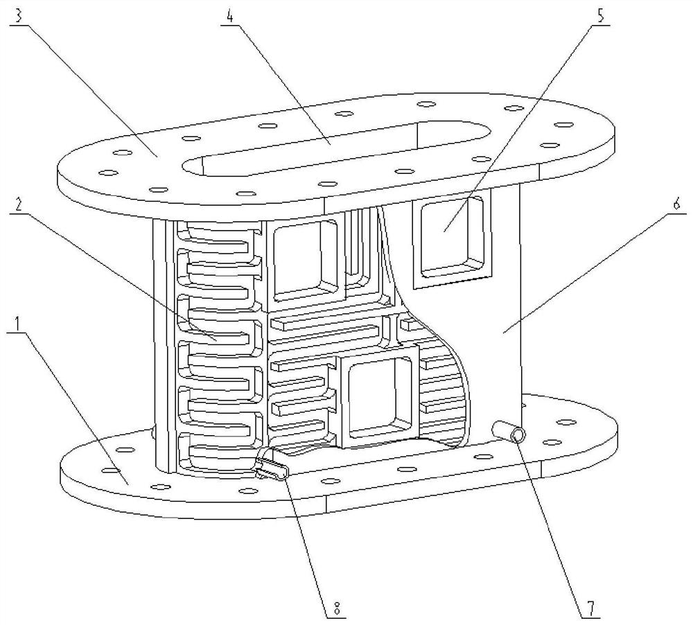
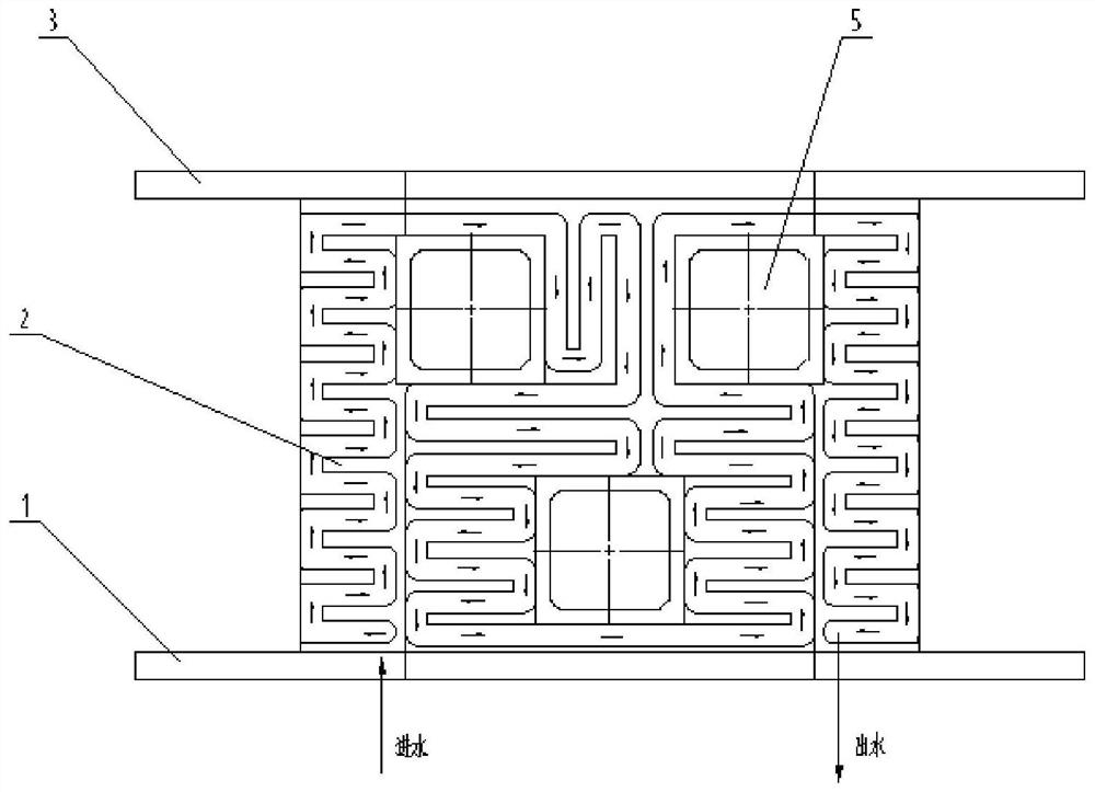
[0021] A high temperature reactor, such as figure 1 , 2 , the outer shell 6 is fixedly connected with the inner shell 4, and a water-proof rib 2 is arranged between the outer shell 6 and the inner shell 4, and a cooling passage for cooling water circulation is formed between the outer shell 6 and the inner shell 4; the outer shell 6 The water inlet pipe 8 and the water outlet pipe 7 are arranged on the top, and the water outlet pipe 7 and the water inlet pipe 8 are connected with the external water source. After the cooling water is injected from the water inlet pipe 8, the cooling water flows through the cooling channel, and the outer shell 6 and the A cooling water passage is formed between the inner shells 4, and then flows out through the outlet pipe 7; the outer shell 6 and the inner shell 4 are provided with through holes 5 for installing heat source equipment. Both the inner shell 4 and the outer shell 6 include arc segments on both sides and a plane segment in the mid...


PUM


Abstract

A high-temperature reaction kettle belongs to the mechanical field. The invention includes an outer shell, an inner shell, water inlet and outlet pipes, an upper flange, a lower flange, and water-proof ribs. The wall of the inner cavity of the inner shell is sprayed with a protective layer. The flow field is uniform. The present invention is a comprehensive high-temperature reaction kettle capable of satisfying working environments such as high temperature resistance, wear resistance, and insulation at the same time. effect and can be mass-produced.

Description

technical field [0001] The invention relates to a high-temperature reaction kettle, which belongs to the field of machinery. Background technique [0002] High-temperature reaction kettles are used in chemical industry, metallurgy, hazardous waste treatment and other industries. The reaction medium includes gas, solid, and gas-solid two-phase mixture. It needs to meet the technological requirements of different working environments such as high temperature resistance, wear resistance, and insulation. In order to facilitate the installation of the heat source generating device, it is necessary to open holes on the heat-resistant wall surface, which increases the difficulty of arranging water channels on the wall surface, or the cooling efficiency is low, which affects the service life of the insulating materials used, or the flow distribution is uneven, resulting in The equipment is partially overheated and burns out; during the reaction process, solid particles will wash awa...

Claims


Application Information

Patent Timeline
Patent Type & Authority Patents(China)
IPC IPC(8): B01J19/00
Inventor 陈峰刘大宝
Owner 航天神洁(北京)科技发展有限公司
Why Eureka
Try Eureka