Cylindrical roller bearing roller vertical inclination and swinging state measuring method

A technology for cylindrical roller bearings and measurement methods, which is applied in the direction of roller bearings, bearings, bearing assembly, etc., and can solve the problems of inaccurate distribution of contact force between rollers and raceways, inaccurate identification of working conditions, etc.

Inactive Publication Date: 2019-05-24
XI AN JIAOTONG UNIV
View PDF3 Cites 4 Cited by
  • Summary
  • Abstract
  • Description
  • Claims
  • Application Information

AI Technical Summary

Problems solved by technology

However, there is still no measurement method and means that can effectively measure the up-and-down swing state of rolling bearing rollers under actual working conditions. Most scholars establish a dynamic model of rolling bearings to simulate the actual working conditions of the bearings, thereby simulating the rolling of the bearings under actual working conditions. Since the actual working conditions are greatly simplified in the dynamic model, although the simulation results have a certain reference value, there is still a big gap between them and the actual working conditions, which leads to the judgment of the bearing roller running state. And the distribution of the contact force between the roller and the raceway during the actual operation is inaccurate, which leads to inaccurate judgment of the overall working state of the bearing. Therefore, it is very necessary to obtain the up and down tilt swing state of the roller under the actual operating condition

Method used


Image

  • Cylindrical roller bearing roller vertical inclination and swinging state measuring method
  • Cylindrical roller bearing roller vertical inclination and swinging state measuring method
  • Cylindrical roller bearing roller vertical inclination and swinging state measuring method

Examples


Embodiment

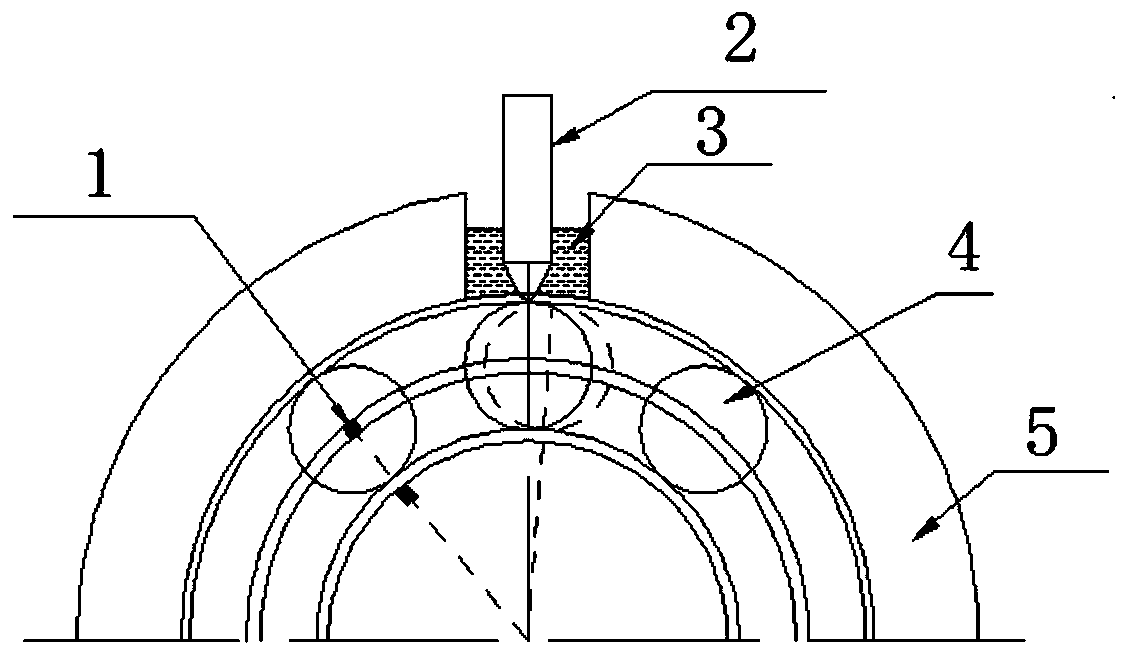
[0045] see figure 1 , is a schematic diagram of the rollers of the cylindrical roller bearing tilting up and down in this example of the present invention, and the rollers of the rolling bearing will tilt to a certain extent during the actual working process.

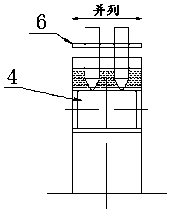
[0046] see figure 2 with image 3 , is a schematic diagram of the installation of the ultrasonic sensor in this example of the present invention, wherein, 1 is a reflective sheet, 2 is an ultrasonic sensor, 3 is water, 4 is a cylindrical roller, 5 is a bearing seat, and 6 is a bracket. Under good coupling conditions, two ultrasonic sensors are installed side by side along the roller length direction just above the outer ring of the bearing. Using double probes to measure in parallel, based on the equivalent stiffness method, the oil film thickness h, ultrasonic signal reflectivity R and incident ultrasonic frequency f can be simplified as a function of formula (1). Through the high-frequency focused ultrasonic senso...


PUM


Abstract

The invention discloses a cylindrical roller bearing roller vertical inclination and swinging state measuring method. The cylindrical roller bearing roller vertical inclination and swinging state measuring method comprises mounting two or more ultrasonic sensors side by side in the length direction of a roller onto the outer circumference of a cylindrical roller bearing, synchronously collecting the ultrasonic reflection signals of the two or more ultrasonic sensors on the contact interface between the inner surface of the outer circumference of the cylindrical roller bearing and the roller, computing the reflective rate of every ultrasonic signal to acquire and convert the rigidity of oil films of different positions into the oil film thickness of corresponding positions, and according tothe relative amplitude of the oil film thickness measured by the two or more ultrasonic sensors, determining the vertical inclination and swinging state of the roller during practical operation and further determining the operation state of the bearing roller as well as distribution of contact force between the roller and a rollerway during practical operation. Therefore, the cylindrical roller bearing roller vertical inclination and swinging state measuring method can provide direct data support for determination of overall working states of bearings as well as contact lubrication theoretical analysis and further improve the level of design, processing and operation of domestic bearings in China.

Description

technical field [0001] The invention belongs to the technical field of bearing running state detection under actual working conditions, and in particular relates to a method for measuring the up and down tilting swing state of a cylindrical roller bearing roller. Background technique [0002] Cylindrical roller bearings are widely used in large rotating machinery such as aero-engines, high-speed trains, fans, and high-speed machine tools due to their advantages such as small friction coefficient, large radial load-carrying capacity, and high rotational accuracy. Its operating performance and stability are closely related to the state of the rollers tilting up and down under actual working conditions. Radial cylindrical roller bearings with ribs on the inner and outer rings can bear certain axial loads, and when bearing axial loads, the rollers tend to incline to a certain extent. In addition, due to installation errors, thermal deformation, geometric shape defects and other...

Claims


Application Information

Patent Timeline
Patent Type & Authority Applications(China)
IPC IPC(8): G01M13/045G01B17/00F16C41/00
CPCF16C19/26F16C41/00F16C2233/00G01B17/02G01M13/045
Inventor 刘恒李猛田桂斌刘意戚社苗陈书恒
Owner XI AN JIAOTONG UNIV
Why Eureka
Try Eureka