Check patentability & draft patents in minutes with Patsnap Eureka AI!

Microcurrent detecting circuit

A detection circuit and micro-current technology, applied in the field of micro-current, can solve problems such as low operating frequency, complicated operation, and large signal-to-noise ratio, and achieve the effect of improving response time

Inactive Publication Date: 2019-05-24
BEIJING JIAOTONG UNIV
View PDF6 Cites 2 Cited by
  • Summary
  • Abstract
  • Description
  • Claims
  • Application Information

AI Technical Summary

Problems solved by technology

The micro-current detection circuit generally uses a high resistance and I-V conversion circuit to realize the output of the micro-current, and converts the micro-current into an easy-to-measure voltage signal. At present, the conversion circuit is widely used, that is, the general large resistance is used to obtain the micro-current. This method is simple to use, but the operation is complicated, and a series of filter circuits need to be added to the circuit, and the circuit is complex, low flexibility, low operating frequency, serious electromagnetic interference, large signal-to-noise ratio, unstable output voltage, etc.

Method used


Image

  • Microcurrent detecting circuit
  • Microcurrent detecting circuit

Examples


Embodiment Construction

[0037] The present invention will be described in further detail below in conjunction with the accompanying drawings.

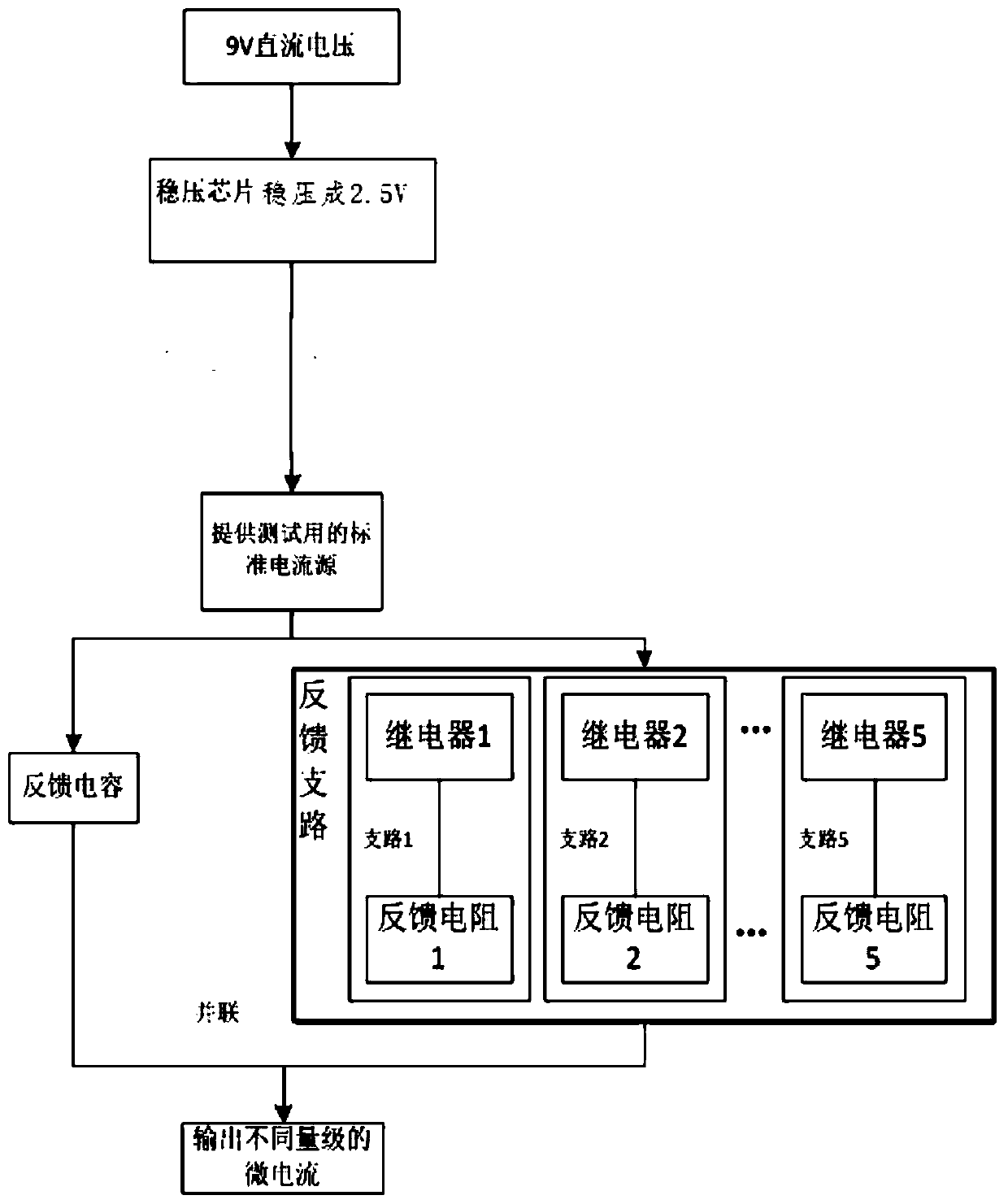
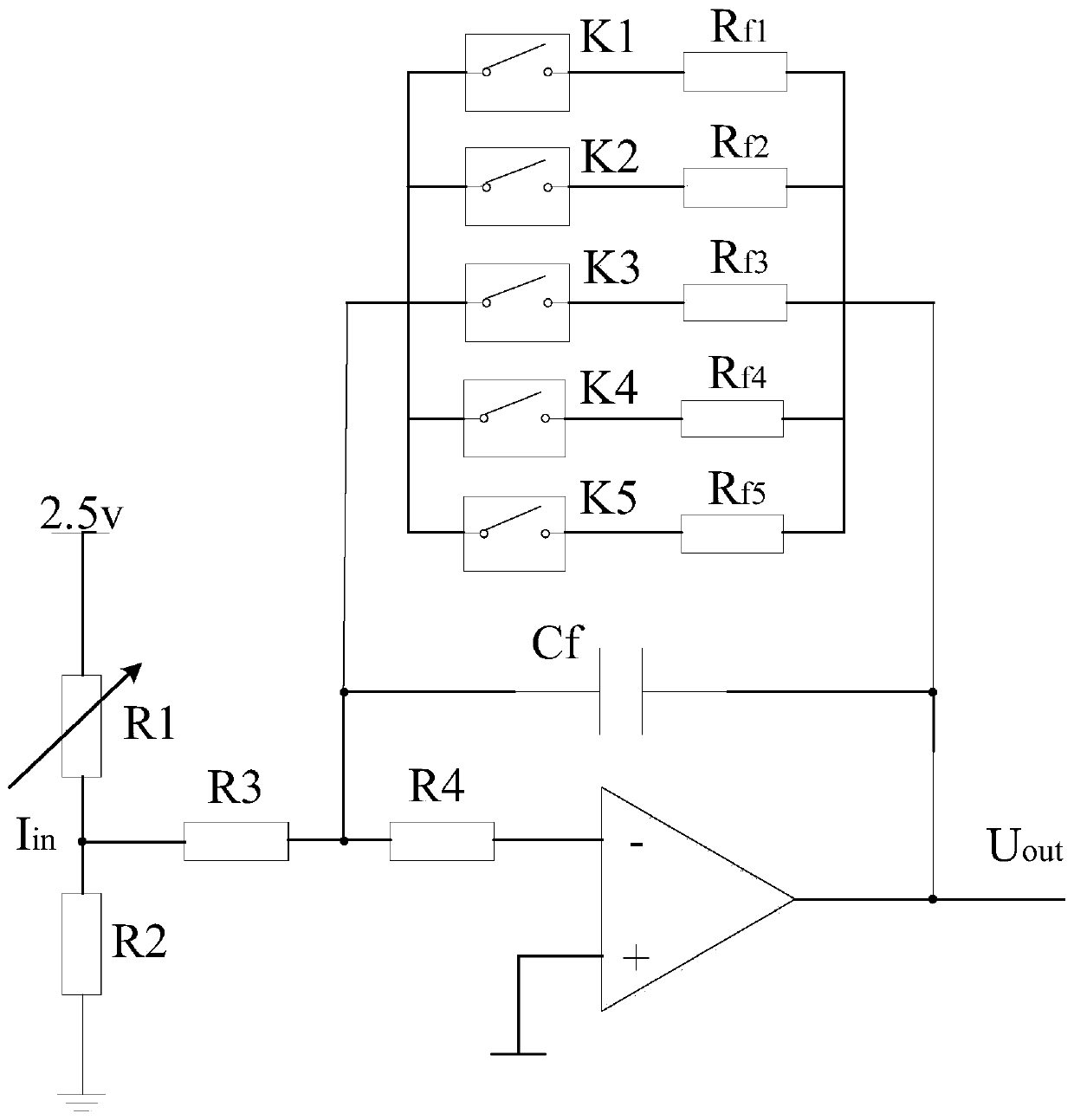
[0038] When measuring micro current, use a high resistance to provide the required fA-level current, and use a high resistance as a feedback resistor to suppress the signal-to-noise ratio and achieve the required stable voltage. Adding a feedback capacitor can offset the influence of the input capacitor and improve the response time , By adding protection resistors, the circuit will not be damaged by accidental overvoltage, adding five feedback branches, and controlling the on-off of each feedback branch relay to achieve the detection of micro-currents of various magnitudes. Through the description of the above circuit, the circuit can output a stable fA level current.

[0039] refer to figure 1 , showing a structural block diagram of an embodiment of microcurrent detection, specifically including the following components:

[0040] Regulator circuit regulat...


PUM


Abstract

The invention provides a microcurrent detecting circuit. The microcurrent detecting circuit comprises an adjustable divider resistance circuit, an I-V conversion circuit and a large resistor R3, wherein the adjustable divider resistance circuit comprises a first resistor R1 and a second resistor R2; the I-V conversion circuit comprises a protecting resistor R4, a feedback capacitor Cf, an operational amplification chip and a relay selecting on-off circuit; the relay selecting on-off circuit comprises a feedback branch I, a feedback branch II, a feedback branch III, a feedback branch IV and a feedback branch V; an adjustable resistor can be changed to control input voltage, feedback resistance can be changed by controlling on and off of every relay, and accordingly current of different orders of magnitude can be achieved; by adjusting the adjustable resistor, the input voltage of a classic negative feedback I-V conversion circuit can be changed, and accordingly the current in the circuit can reach the order of magnitude of fA to achieve microcurrent detection.

Description

technical field [0001] The invention relates to the technical field of micro-current, in particular to a micro-current detection circuit, which uses the on-off of a relay to detect micro-currents of different magnitudes, and relates to an I-V conversion circuit. Background technique [0002] In practical applications, the micro-current detection circuit is usually a detection technology for noise. This technology has a wide range of applications in military investigation, physics, chemistry, electrochemistry, biomedicine, astronomy, geology, magnetism and many other fields. Micro-current detection is to evaluate the condition of insulating materials through the measurement of leakage current or to detect the required signal through the micro-current in the sensor. The micro-current detection circuit generally uses a high resistance and I-V conversion circuit to realize the output of the micro-current, and converts the micro-current into an easy-to-measure voltage signal. At ...

Claims


Application Information

Patent Timeline
IPC IPC(8): G01R19/00
Inventor 沈海阔汪东军范冬雨
Owner BEIJING JIAOTONG UNIV
Features
  • R&D
  • Intellectual Property
  • Life Sciences
  • Materials
  • Tech Scout
  • Unparalleled Data Quality
  • Higher Quality Content
  • 60% Fewer Hallucinations
Learn More