
CSIW transmission line based on mode conversion

A mode conversion and transmission line technology, applied in waveguides, circuits, electrical components, etc., can solve problems such as large fluctuations in insertion loss, unsatisfactory transmission performance, and limited application range, and achieve miniaturization, long bandwidth, and widening applications range effect

Inactive Publication Date: 2019-05-24
XIDIAN UNIV
View PDF0 Cites 4 Cited by
  • Summary
  • Abstract
  • Description
  • Claims
  • Application Information

AI Technical Summary

Problems solved by technology

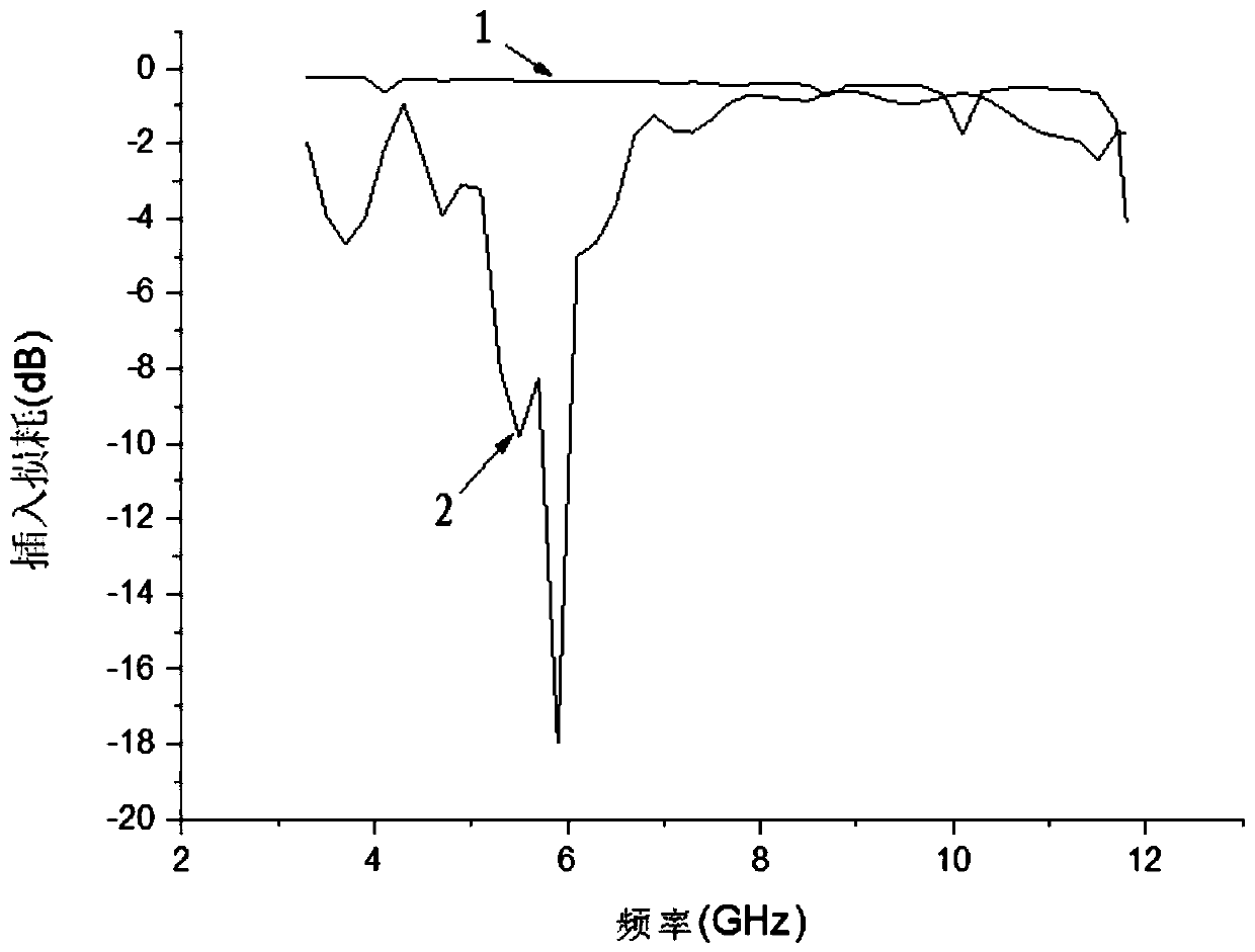
[0004] However, when the frequency is low, the CSIW transmission line can be approximated as a microstrip transmission line with stubs loaded on both sides, and the insertion loss fluctuates greatly. At high frequencies, its transmission performance is also very unsatisfactory due to the influence of high-order modes.
Therefore, under the influence of these two factors, the transmission bandwidth of CSIW is relatively narrow, which limits its application range.

Method used


Image

  • CSIW transmission line based on mode conversion
  • CSIW transmission line based on mode conversion
  • CSIW transmission line based on mode conversion

Examples


Embodiment Construction

[0027] The technical solutions in the embodiments of the present invention will be clearly and completely described below in conjunction with the accompanying drawings in the embodiments of the present invention. Obviously, the described embodiments are only a part of the embodiments of the present invention, rather than all the embodiments.

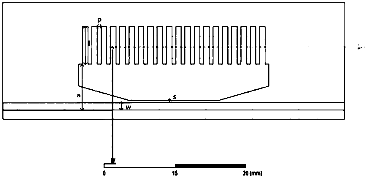
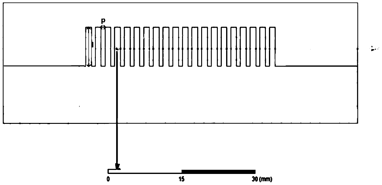
[0028] The embodiment of the present invention provides a CSIW transmission line based on mode conversion, including a dielectric substrate, and a top metal layer and a bottom metal layer respectively disposed on the upper and lower surfaces of the dielectric substrate; the metal layer in this embodiment is a copper layer, that is, The upper and lower surfaces of the dielectric substrate are covered with a layer of metallic copper.

[0029] reference figure 1 with figure 2 A plurality of open branches are arranged on one side of the top metal layer and the bottom metal layer respectively, wherein the multiple open branches are arranged parall...


PUM


Abstract

The invention discloses a CSIW transmission line based on mode conversion. The CSIW transmission line comprises a dielectric substrate, a top metal layer and a bottom metal layer, wherein the top metal layer and the bottom metal layer are respectively arranged on the upper and lower surfaces of the dielectric substrate. A plurality of open circuit branches are correspondingly arranged on one sideof each of the top metal layer and the bottom metal layer in the up and down manner. A long-strip-shaped gap is formed in one side, far away from the open circuit branches, of the top metal layer. A central conduction band is arranged on one side, far away from the open circuit branches, of the long-strip-shaped gap. The CSIW transmission line based on mode conversion has two transmission modes. Compared with a traditional CSIW, the overall size of the CSIW transmission line is reduced by nearly a half. Moreover, the bandwidth of the CSIW transmission line is wider, and the insertion loss andthe return loss of the CSIW transmission line are better.

Description

Technical field [0001] The invention relates to the technical field of microwave transmission lines, in particular to a CSIW transmission line based on mode conversion. Background technique [0002] In recent years, microwave transmission line technology has developed rapidly. Following the emergence of transmission lines such as waveguides, microstrip lines, and slot lines, a new type of microwave transmission line substrate integrated waveguide (SIW) has also appeared. The traditional microstrip line has the advantages of small size and easy integration with planar circuits; but on the other hand, due to its semi-open structure, the radiation loss of the microstrip transmission line becomes very large when the frequency is relatively high, which leads to the high frequency of the microstrip line. Frequent applications are restricted. The traditional rectangular waveguide has the advantages of large power capacity and low loss, so it is widely used at high frequencies; but on ...

Claims


Application Information

Patent Timeline
Patent Type & Authority Applications(China)
IPC IPC(8): H01P3/10
Inventor 李磊白峻恺
Owner XIDIAN UNIV
Learn More