
Gas-liquid separation device for de-foaming gas

A gas-liquid separation device and defoaming technology, applied in the field of multiphase flow separation, can solve the problems of natural gas entrained foam, etc., and achieve the effects of curbing the generation of secondary foam, reducing costs, and reducing pipeline liquid accumulation

Pending Publication Date: 2019-05-28
CHINA UNIV OF PETROLEUM (BEIJING)
View PDF0 Cites 13 Cited by
  • Summary
  • Abstract
  • Description
  • Claims
  • Application Information

AI Technical Summary

Problems solved by technology

[0005] This application provides a gas-liquid separation device for gas defoaming, to at least solve the problem of a large amount of foam entrained in natural gas in the prior art

Method used


Image

  • Gas-liquid separation device for de-foaming gas
  • Gas-liquid separation device for de-foaming gas
  • Gas-liquid separation device for de-foaming gas

Examples


Embodiment Construction

[0052] The following will clearly and completely describe the technical solutions in the embodiments of the application with reference to the drawings in the embodiments of the application. Apparently, the described embodiments are only some of the embodiments of the application, not all of them. Based on the embodiments in this application, all other embodiments obtained by persons of ordinary skill in the art without making creative efforts belong to the scope of protection of this application.

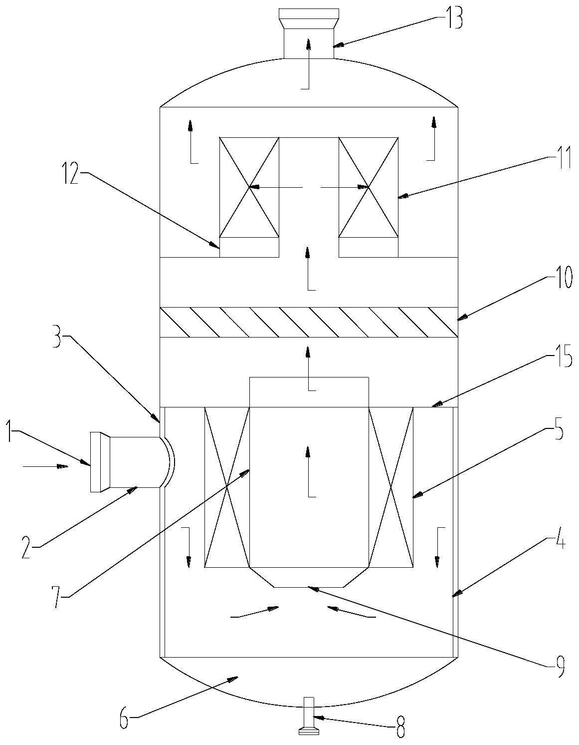
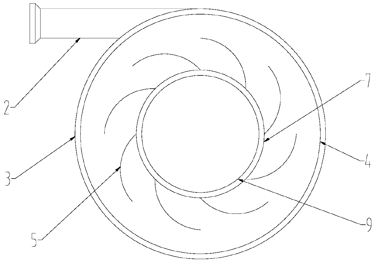
[0053] In order to solve the problems in the prior art, the application proposes a gas-liquid separation device for gas defoaming, such as figure 1 As shown, the gas-liquid separation device is mainly composed of a swirl shell 3, a centrifugal defoaming component and a secondary chemical defoaming component arranged in the swirl shell 3, and the centrifugal defoaming component is placed in the swirl shell 3, the secondary chemical defoaming component is placed on the upper part of t...


PUM


Abstract

The invention provides a gas-liquid separation device for de-foaming gas. The gas-liquid separation device comprises a cyclone shell body, and a centrifugal de-foaming part and a secondary chemical de-foaming part which are arranged in the cyclone shell body, wherein the centrifugal de-foaming part is arranged at the lower part of the cyclone shell body and comprises a cyclone inner barrel, and arotary blade assembly and an exhausting pipe which are arranged in the cyclone inner barrel; the rotary blade assembly sleeves the outer side of the exhausting pipe; the secondary chemical de-foamingpart is arranged at the upper part of the cyclone shell body and comprises a de-foaming net arranged above the cyclone inner barrel in the device, and a corrugated plate arranged above the de-foamingnet. De-foaming methods including a centrifugal field, inertial impaction, super-hydrophobic surfaces and the like are reasonably and effectively matched together, and rapid de-foaming can be realizedthrough combining a mechanical method and a chemical de-foaming mechanism; compared with an existing chemical de-foaming method, the operation cost is greatly reduced and a pre-separation process ofgas and liquid phases also can be realized, so that the generation of secondary foam can be effectively reduced.

Description

technical field [0001] This application relates to the technical field of multiphase flow separation, in particular to the defoaming operation and gas-liquid pre-separation process used in the natural gas foam drainage gas recovery process. Background technique [0002] The existing foam drainage gas recovery technology is a better technology for removing bottom-hole fluid in the middle and late stages of natural gas (including shale gas) production. However, before the natural gas enters the gas pipeline, if the large amount of stable foam entrained in it is not removed in time, it will cause certain damage to the pipeline transportation equipment and measuring instruments, and at the same time seriously affect the liquid removal effect of the gas-liquid separation equipment. Affect the safe operation of the gas transmission system. [0003] First-line stations usually use chemical defoaming methods to implement defoaming operations, that is, through skid-mounted injection...

Claims


Application Information

Patent Timeline
IPC IPC(8): B01D45/14B01D45/08B01D45/04B01D50/00C10L3/10
Inventor 常程王佳荣姬忠礼刘震
Owner CHINA UNIV OF PETROLEUM (BEIJING)
Learn More