External stray light testing device and method of infrared optical system

An infrared optical system and testing device technology, applied in the optical field, can solve the problems of errors, complex systems, few types, etc., and achieve the effect of meeting the testing requirements

Pending Publication Date: 2019-05-28
CHANGCHUN UNIV OF SCI & TECH
View PDF0 Cites 3 Cited by
  • Summary
  • Abstract
  • Description
  • Claims
  • Application Information

AI Technical Summary

Problems solved by technology

Windows, debris, optics and even sensors can cause unintentional radiation to hit the detector
This light can overwhelm the desired signal and introduce calculation errors, greatly affecting the imaging quality of the infrared optical system
At present, there are few types of external stray light test systems for infrared optical systems, and most of them have complex systems, high prices, and cannot qualitatively and quantitatively analyze the external stray light of infrared optical systems.

Method used


Image

  • External stray light testing device and method of infrared optical system
  • External stray light testing device and method of infrared optical system
  • External stray light testing device and method of infrared optical system

Examples


Embodiment Construction

[0028] In order to make the technical solutions and beneficial effects of the present invention clearer, the present invention will be further described in detail below in conjunction with the accompanying drawings and embodiments. It should be understood that the specific embodiments described here are only used to explain the present invention, not to limit the present invention.

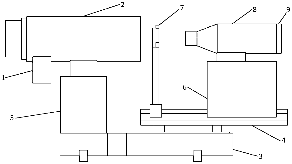
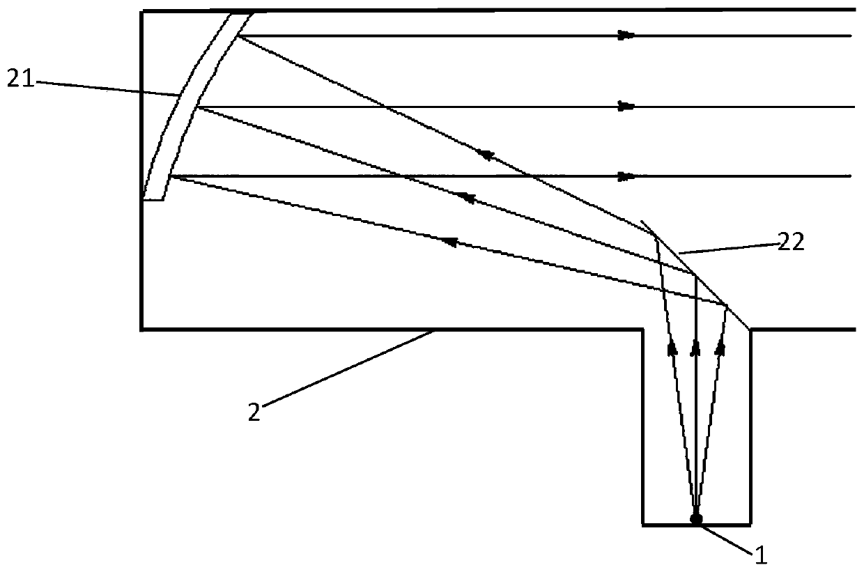
[0029] like figure 1 and figure 2 As shown, an infrared optical system external stray light test device includes a light source 1, a collimator 2, a turntable 3, a sliding guide rail 4, a first bracket 5, a second bracket 6, a lens mount 7, a microscope system 8, Detector 9, the light source 1 is installed below the collimator 2, the collimator 2 includes a primary reflector 21 and a secondary reflector 22, the turntable 3 and the collimator 2 are connected by a first bracket 5 , the sliding guide rail 4 is installed on the turntable 3, the lens mount 7 and the second bracket 6 are installed on...


PUM


Abstract

The invention discloses an external stray light testing device and method of an infrared optical system. The external stray light testing device comprises a light source, a collimator, a rotary table,a sliding guide rail, a first bracket, a second bracket, a lens mounting seat, a microscope system and a detector; during a test, the external stray light testing device of the infrared optical system is placed in a darkroom, light rays of the light source are reflected by a secondary reflecting mirror and main reflecting mirror in the collimator in sequence and changed into parallel beams, the collimator, the infrared optical system, the microscope system and the detector are located on a same optical axis through adjustment, the detector records image data, external stray light is introduced from different perspectives respectively, and the detector records the image data repeatedly. The external stray light testing device and method of the infrared optical system have the advantages that the principle is simple, various medium-wave infrared optical systems are in common use, the external stray light of the infrared optical system can be measured qualitatively and quantitatively, and the inhibition level of the external stray light by the infrared optical system is accurately evaluated.

Description

technical field [0001] The invention relates to the field of optics, in particular to an infrared optical system external stray light testing device and testing method. Background technique [0002] Stray light refers to the non-imaging light that reaches the image surface of the optical system. The impact on the optical system, especially the cooling infrared optical system, is mainly manifested in: the contrast of the image surface decreases, the image sharpness becomes smaller, and the image quality deteriorates, which causes MTF. Degradation and the reduction of the effective signal-to-noise ratio of the system can lead to the inability to accurately identify targets in severe cases. For cooled infrared optical systems, the level of external stray light suppression is one of the key factors to judge its imaging quality and affect the target recognition ability of the photoelectric system. [0003] Manufacturers are currently requiring space optics systems to take on mor...

Claims


Application Information

Patent Timeline
Patent Type & Authority Applications(China)
IPC IPC(8): G01M11/02G02B17/06
Inventor 高少华徐熙平刘智颖李岩岩宣雅萍
Owner CHANGCHUN UNIV OF SCI & TECH
Why Eureka
Try Eureka