A reference clock frequency multiplier circuit and algorithm based on numerical control delay duty ratio calibration

A duty cycle and duty cycle detection technology, which is applied in the field of analog integrated circuits and radio frequency design, can solve the problems of cumbersome, large frequency multiplication noise, and poor output signal phase noise performance, and achieve small area, low power consumption, and suitable Good matching effect

Active Publication Date: 2019-05-28
ZHEJIANG UNIV
View PDF8 Cites 8 Cited by
  • Summary
  • Abstract
  • Description
  • Claims
  • Application Information

AI Technical Summary

Problems solved by technology

Due to the large number of harmonics generated during the nonlinear transformation process, the phase of the output signal is unstable, and the frequency multiplier composed of nonlinear devices usually has a large frequency noise.
It is too cumbersome to use the principle of phase-locked loop for frequency multiplication to provide a reference clock for another phase-locked loop
When using an XOR gate for frequency multiplication, if the duty cycle of the input signal deviates from 50%, the phase noise performance of the output signal will be poor, so its application is limited

Method used


Image

  • A reference clock frequency multiplier circuit and algorithm based on numerical control delay duty ratio calibration
  • A reference clock frequency multiplier circuit and algorithm based on numerical control delay duty ratio calibration
  • A reference clock frequency multiplier circuit and algorithm based on numerical control delay duty ratio calibration

Examples


Embodiment Construction

[0023] The present invention will be further elaborated below in conjunction with the accompanying drawings and specific embodiments.

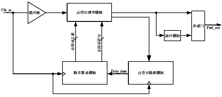
[0024] The XOR gate frequency multiplier structure with digital duty cycle calibration of the present invention is as follows figure 1 Shown:

[0025] The externally supplied clock signal enters the buffer, and also enters the digital algorithm module and the duty ratio detection module to provide the clock signal through its internal frequency division. The output signal of the buffer enters the duty ratio adjustment module, and the first output of the duty ratio adjustment module The signal is divided into two channels and enters the delay module and the XOR gate respectively, wherein the output signal of the delay module also enters the XOR gate, and the XOR gate outputs a double frequency signal; the second output signal of the duty cycle adjustment module is controlled by the duty cycle The detection module monitors, and the duty cycle d...


PUM


Abstract

The invention discloses a reference clock frequency multiplier circuit and algorithm based on numerical control delay duty ratio calibration. External clock signals respectively enter the buffers, a digital algorithm module and a duty ratio detection module; a buffer output signal enters the duty ratio adjusting module; A first output signal of the duty ratio adjusting module is divided into two paths to enter the time delay module and the exclusive-OR gate respectively. an output signal of the delay module also enters the XOR gate; the exclusive-OR gate outputs a frequency-doubled signal; a second output signal of the duty ratio adjusting module is monitored by the duty ratio detecting module; the duty ratio detection module compares the current duty ratio with 50%; and a duty ratio indication signal Duty _ data is output to the digital algorithm module, the digital algorithm module executes an algorithm according to the Duty _ data input signal, and an output control word adjustmentcontrol word and a jitter control word of the algorithm are output to the duty ratio adjustment module to form a loop. Compared with a traditional analog duty ratio adjusting circuit, the circuit hasthe advantages of being small in area, low in power consumption and good in application requirement adaptability.

Description

technical field [0001] The present invention designs the field of radio frequency and analog integrated circuits, relates to a frequency synthesizer based on a phase-locked loop and a frequency multiplier based on an XOR gate, especially a reference clock frequency multiplier circuit and algorithm based on numerical control delay duty cycle calibration . Background technique [0002] At present, most frequency synthesizers use an analog phase-locked loop structure, and the phase noise of the output signal is usually affected by the reference clock frequency and frequency division ratio. For an integer frequency synthesizer, its total output phase noise in the s domain is shown in formula (1): [0003] [0004] Among them, N represents the frequency division ratio of the frequency divider in the phase-locked loop, H o (s) represents the open-loop transfer function of the phase-locked loop, K VCO Indicates the tuning gain of the VCO, represents the total output phase n...

Claims


Application Information

Patent Timeline
Patent Type & Authority Applications(China)
IPC IPC(8): H03L7/16H03K3/017
Inventor 陈嘉豪李浩明王腾佳郁发新王志宇
Owner ZHEJIANG UNIV
Why Eureka
Try Eureka