
Automatic cleaning machine

An automatic cleaning machine and chassis technology, which is applied in the field of cleaning machines, can solve the problems of poor chip blowing efficiency, flying waste chips, and low degree of mechanization, and achieve the effect of solving the dead angle of blowing, saving manpower and material resources, and strong chip removal ability

Inactive Publication Date: 2019-05-31
江苏贺鸿电子有限公司
View PDF9 Cites 7 Cited by
  • Summary
  • Abstract
  • Description
  • Claims
  • Application Information

AI Technical Summary

Problems solved by technology

[0003] The current blower cleaning machine used for plate cleaning has poor cleaning effect, incomplete cleaning, and low degree of mechanization, which cannot completely remove waste chips on the surface of the material, and the protection performance is poor when blowing chips, which may easily cause waste chips to fly randomly. phenomenon, and the air blowing port cannot swing, which makes it less efficient in chip blowing, and the collection of waste chips is not perfect, which increases the workload of the staff

Method used


Image

  • Automatic cleaning machine
  • Automatic cleaning machine
  • Automatic cleaning machine

Examples


Embodiment Construction

[0020] The following will clearly and completely describe the technical solutions in the embodiments of the present invention with reference to the accompanying drawings in the embodiments of the present invention. Obviously, the described embodiments are only some, not all, embodiments of the present invention. Based on the embodiments of the present invention, all other embodiments obtained by persons of ordinary skill in the art without making creative efforts belong to the protection scope of the present invention.

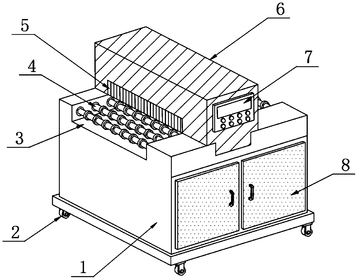
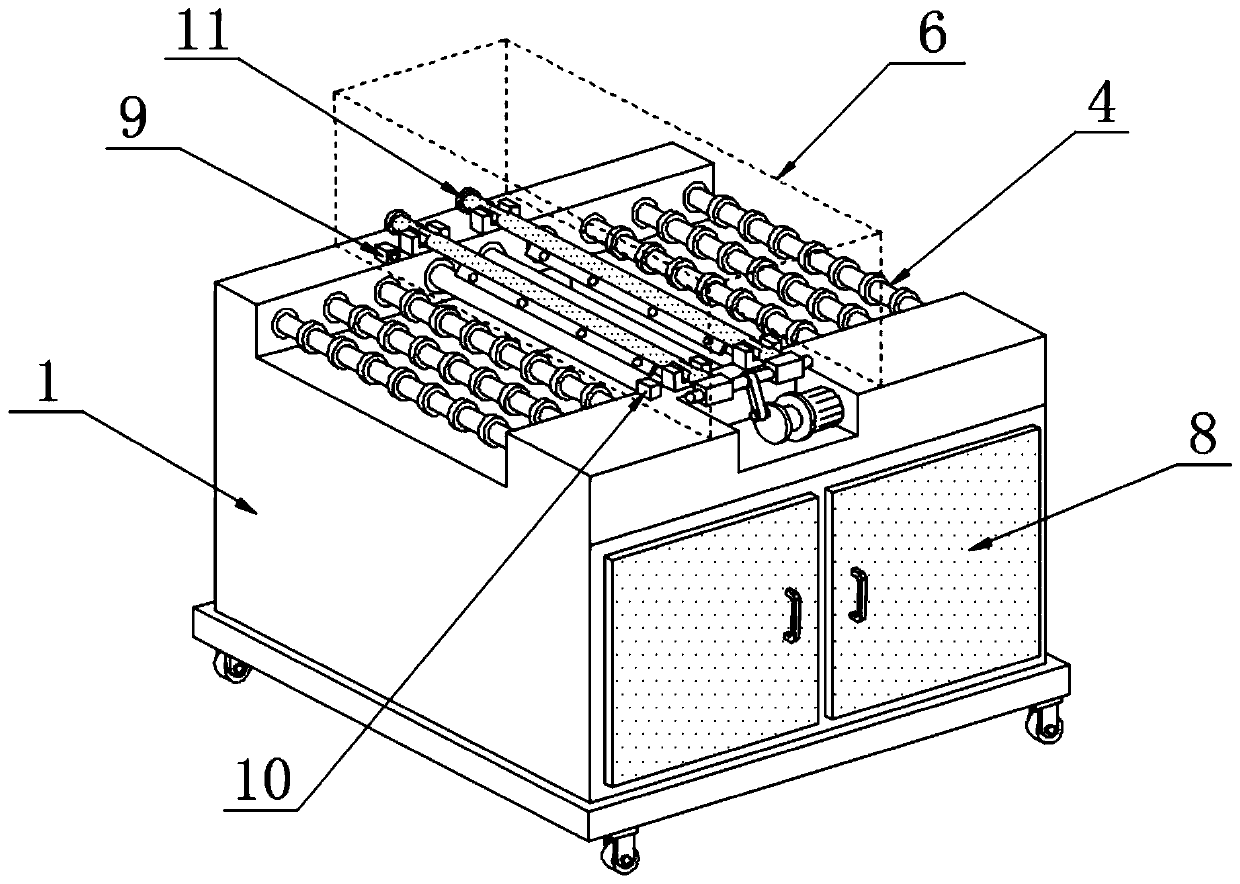
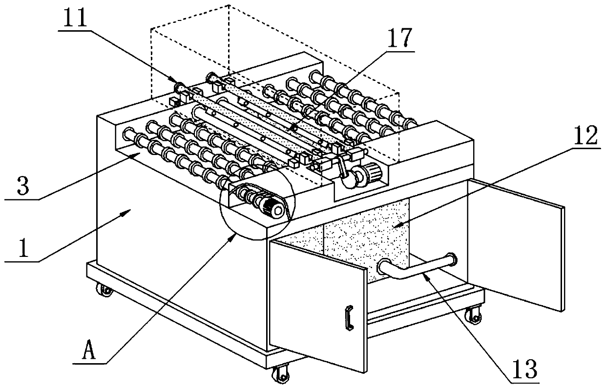
[0021] see Figure 1~5 , in an embodiment of the present invention, an automatic cleaning machine includes a chassis 1 and four corners of the lower end of the chassis 1 are provided with pulleys 2 for moving, and the upper end of the chassis 1 is provided with a transmission groove 3 in the shape of "凵", And the upper end of cabinet 1 is positioned at the inboard position of conveying groove 3 and is equipped with the conveying roller 4 that is used for conve...


PUM


Abstract

The invention discloses an automatic cleaning machine and relates to the technical field of cleaning machines. The automatic cleaning machine comprises a chassis and moving pulleys arranged at four corners at the lower end of the chassis, wherein an inverted n-shaped conveying groove is formed in the upper end of the chassis; and a conveying roller for conveying material is mounted at the upper end, positioned on the inner side of the conveying groove, of the chassis. The automatic cleaning machine adopts the photoelectricity sensing manner to automatically sense the material and automaticallystart an air blowing structure; in addition, double rows of air-blowing ports can thoroughly blow off sweeps on the material; swing type automatic compressed air injection sweep removal is cooperatedwith the air-blowing ports designed by 60 degrees obliquely, so that the purposes of being large in coverage area, small in compressed air emission and extremely high in sweep removing capacity are realized, and the problem the air blowing dead angle problem is solved; and moreover, a transparent air-blowing mask and a windproof curtain are adopted to prevent the phenomenon that sweeps fly everywhere during the sweep blowing process, and the material sweep removal efficiency is further improved.

Description

technical field [0001] The invention relates to the technical field of washing machines, in particular to an automatic washing machine. Background technique [0002] The cleaning machine is used to wash and filter the pollutants generated or intruded during the manufacturing, assembly, use and maintenance of the hydraulic system; it can also be used for regular maintenance and filtration of working oil to improve cleanliness and avoid or reduce pollution caused by pollution. failure, thus ensuring the high performance, high reliability and long life of the hydraulic system equipment. [0003] The current blower cleaning machine used for plate cleaning has poor cleaning effect, incomplete cleaning, and low degree of mechanization, which cannot completely remove waste chips on the surface of the material, and the protection performance is poor when blowing chips, which may easily cause waste chips to fly randomly. The phenomenon, and the blowing port can not realize the swing...

Claims


Application Information

Patent Timeline
IPC IPC(8): B08B5/02B08B15/00
Inventor 刘统发
Owner 江苏贺鸿电子有限公司
Learn More