Solid wood numerical control machining center and control system and machining method of solid wood numerical control machining center

A machining center, solid wood technology, applied in the field of CNC machine tools, can solve problems such as restricting the development of intelligent milling of CNC equipment, and achieve the effect of ensuring strength, smooth transmission, and precise speed change

Active Publication Date: 2019-05-31
NANXING MACHINERY CO LTD
View PDF10 Cites 2 Cited by
  • Summary
  • Abstract
  • Description
  • Claims
  • Application Information

AI Technical Summary

Problems solved by technology

In addition, the same equipment can realize different processing methods and different control systems. How to realize the most efficient processing method and can realize it through the control system requires more effort than the mechanical structure for those skilled in the art. Creative labor also restricts the development of traditional CNC equipment to intelligent milling

Method used


Image

  • Solid wood numerical control machining center and control system and machining method of solid wood numerical control machining center
  • Solid wood numerical control machining center and control system and machining method of solid wood numerical control machining center
  • Solid wood numerical control machining center and control system and machining method of solid wood numerical control machining center

Examples


Embodiment 1

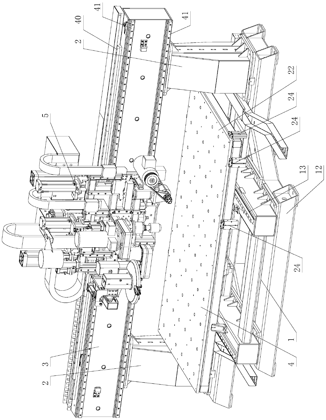
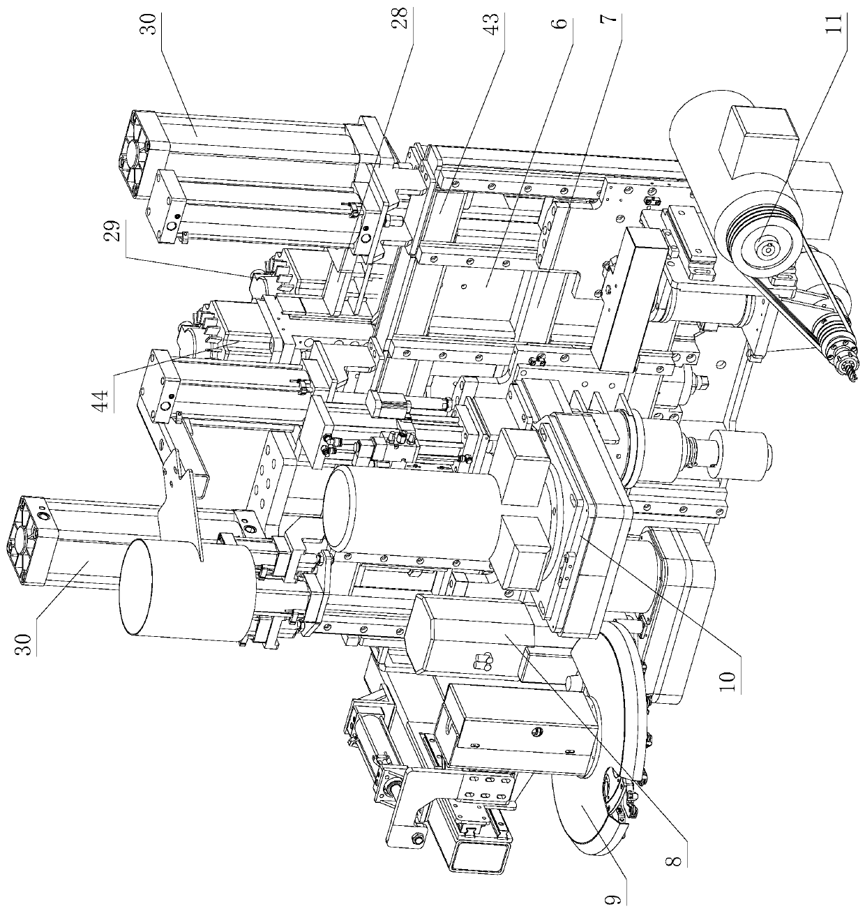
[0120] Such as figure 1 , image 3 , Figure 4 As shown, a solid wood CNC machining center includes a base 1, two columns 2 fixed on the left and right sides of the base 1 arranged in the X direction, and a beam 3 fixed on the two columns 2, which is installed on the base 1 and can be opposite to the base 1 The workbench device 4 that slides back and forth in the Y direction, the head device 5 that is installed on the beam 3 and can slide back and forth in the X direction relative to the beam 3; the head device 5 includes the X-direction slide assembly 6 and the Z-direction large slide assembly 7 , Routing and milling device 8, router device 9, vertical axis milling device 10, horizontal milling device 11.

[0121] Such as figure 1 As shown, the base 1 includes a lower base 12 and an upper base 13 .

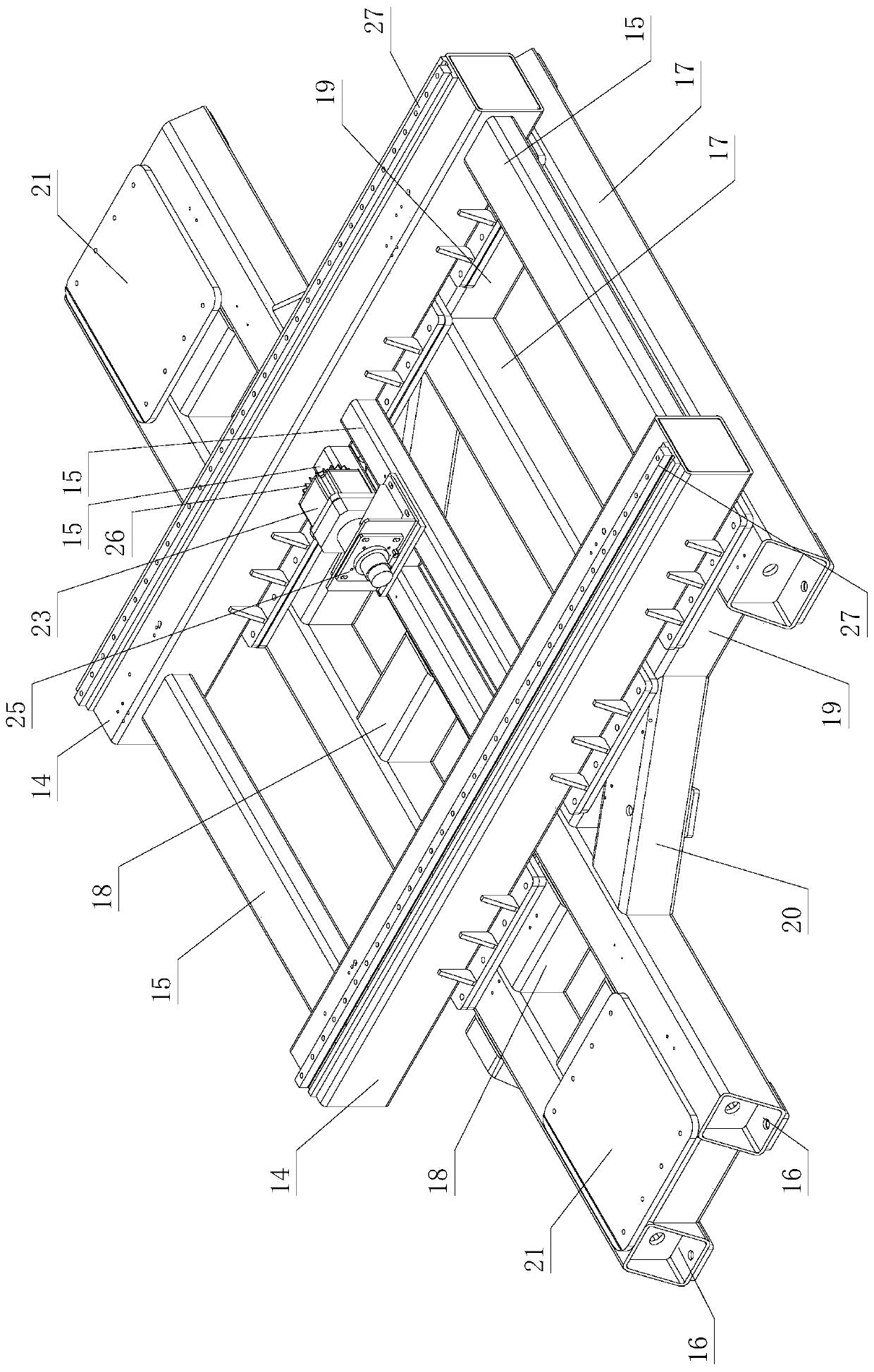
[0122] Such as figure 2 As shown, the upper base 13 includes two Y-direction large square tubes 14, four X-direction small square tubes 15 welded to connect the two Y-direc...

Embodiment 2

[0214] Such as Figure 13 to Figure 15 As shown, a control system of a CNC machining center includes a CNC controller, a data bus and a control bus connected to the CNC controller, a servo control unit connected in parallel with the data bus and the control bus for bidirectional control, a machine head control unit, and a working Station control unit, strong and weak current control unit, man-machine dialogue interface unit, communication unit.

[0215] The servo control unit includes the Y-axis feed servo system that drives the table to slide back and forth along the base in the Y direction, drives the X-axis feed servo system that drives the X-direction slide seat to slide back and forth along the beam in the X direction, and drives the Z-direction large slide seat to slide relative to the X direction. The Z-axis feed servo system that slides back and forth in the Z direction; the P-axis feed servo system that drives the cutter head with multiple clamping mechanisms to rotat...


PUM


Abstract

The invention provides a solid wood numerical control machining center and a machining method of the solid wood numerical control machining center. The solid wood numerical control machining center comprises a base, stand columns, a cross beam, a workbench device and a machine head device. The machine head device comprises an X-axis sliding seat assembly, a Z-axis large sliding seat assembly, a routing device, a routing cutter magazine device, a vertical shaft milling device and a horizontal milling device. The vertical shaft milling device comprises a cutter beating mechanism. The control system comprises a CNC controller, a servo control unit and a machine head control unit. The solid wood numerical control machining center has the advantages that all the machining devices cannot interfere with one another, and multiple kinds of machining such as routing, milling, planing and drilling can be achieved, and a curved face of a workpiece can be machined. The machine head control unit comprises a routing motorized spindle drive unit, a routing lifting control unit, a cutter head movement control unit, a vertical shaft milling spindle drive unit, a vertical shaft milling lifting control unit, a cutter beating control unit, a horizontal milling spindle drive unit, a horizontal milling lifting control unit, a horizontal milling spindle steering control unit and a horizontal milling spindle locating control unit. The solid wood numerical control machining center has the advantages of having universality, high compatibility and high transportability.

Description

technical field [0001] The present invention relates to the field of CNC machine tools for woodworking and its analogues, in particular to a large-scale and precise solid wood CNC machining center with functions such as milling, planing, and drilling, and a high-grade CNC system, as well as its control system and processing method . Background technique [0002] For the processing of solid wood, it is necessary to carry out engraving and milling on the workpiece through engraving and milling devices or equipment, and multi-angle processing such as sawing, side milling and drilling of the workpiece is required with planing and planing devices or equipment. [0003] In the invention patent with the patent number of 201810127805.0 and the public announcement date of July 3, 2018, a multifunctional solid wood processing equipment for milling and planing is disclosed, including a base, a workbench and a beam frame fixed on the base, and the beam The frame is equipped with a slid...

Claims


Application Information

Patent Timeline
Patent Type & Authority Applications(China)
IPC IPC(8): B27C5/10B27C9/00B27C9/04
Inventor 赵莉莉邱宇赖正友秦振伟林旺南闫河江
Owner NANXING MACHINERY CO LTD
Why Eureka
Try Eureka